E-Archive
Science Update
in Vol. 14 - July Issue - Year 2013
Enhancing the Resistance to Hydrogen Embrittlement in Stainless Steel by Cavitation Peening

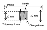
Fig. 1 Geometry and dimensions of specimen for plate bending fatigue test
![Fig. 2 Nozzle for cavitating jet in air [9]](https://www.mfn.li/storage/e-archives/article-pictures/1282/3553.gif)
Fig. 2 Nozzle for cavitating jet in air [9]

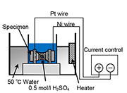
Fig. 3 Cathodic hydrogen-charging apparatus
![Fig. 4 Introduction of compressive
residual stress by cavitation peening [10]](https://www.mfn.li/storage/e-archives/article-pictures/1282/3555.gif)
Fig. 4 Introduction of compressive residual stress by cavitation peening [10]
![Fig. 5 Suppression of hydrogen-assisted fatigue crack growth by cavitation peening [10]](https://www.mfn.li/storage/e-archives/article-pictures/1282/3556.gif)
Fig. 5 Suppression of hydrogen-assisted fatigue crack growth by cavitation peening [10]

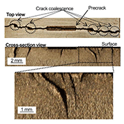
(a) With hydrogen charging (after failure)
![(b) Without hydrogen charging
(after failure)
Fig. 6 Aspects of hydrogen-assisted fatigue crack growth [10]](https://www.mfn.li/storage/e-archives/article-pictures/1282/3558.gif)
(b) Without hydrogen charging (after failure) Fig. 6 Aspects of hydrogen-assisted fatigue crack growth [10]
![Fig. 7 Load-displacement curve varied by H-charging [11]](https://www.mfn.li/storage/e-archives/article-pictures/1282/3559.gif)
Fig. 7 Load-displacement curve varied by H-charging [11]
![Fig. 8 Effect of compressive residual stress on hydrogen-induced surface hardening [11]](https://www.mfn.li/storage/e-archives/article-pictures/1282/3560.gif)
Fig. 8 Effect of compressive residual stress on hydrogen-induced surface hardening [11]
Introduction
A society based on alternative energy sources instead of fossil fuels needs to be constructed in order to reduce greenhouse gasses having an environmental load. Hydrogen has a potential to be the alternative energy source for realizing that society, since it represents a clean, movable and abundant energy carrier. The society based on hydrogen energy is called "hydrogen society". While hydrogen can be utilized as a clean energy resource as mentioned above, it makes metallic material brittle, i.e., Hydrogen Embrittlement [1]. Metallic materials should be used so as to construct infrastructure for hydrogen energy utilization. So, the resistance of metals to hydrogen embrittlement has to be improved. Hydrogen diffuses in accordance with hydrostatic stress gradient and then concentrates around a crack tip where hydrostatic stress has maximum impact [2]. Concentration of hydrogen may promote slip due to interaction between hydrogen and dislocation, accelerating fatigue crack growth [3]. If hydrostatic stress can be changed, the acceleration of fatigue crack growth will be suppressed.
At the same time, peening technique can introduce equibiaxial compressive residual stress field at the surface, enhancing fatigue property [4,5]. Therefore, there is a possibility that peening can suppress hydrogen effect on the fatigue crack growth. For application of peening to suppress this, two factors should be mainly considered. One is surface roughness, and the other is increase in dislocations and/or defects that trap hydrogen. In order to avoid those negative factors, cavitation peening [6,7] can be suitable, since the treated surface is much smoother and increase in dislocation is less than other peening techniques. Peening introduces compressive residual stress by work-hardening caused by impact. Cavitation peening (CP) utilizes the impact produced by cavitation bubbles collapsing. There are no collisions between solid bodies like shot peening. Also, interestingly, CP reduces micro-strain, which is closely related to dislocation induced by heat treatment [8]. Several unknown favorable effects of CP still exist. Introduction of compressive residual stress may suppress both hydrogen invasion and hydrogen concentration around a crack tip due to narrowing lattice spacing, which might make it harder for hydrogen to invade and diffuse in the material.
In this study, the material under test was made of austenitic stainless steel (Japan industrial standards JIS SUS316L), hydrogen charging was done after CP, and then a fatigue crack growth test was conducted by using a plate bending fatigue tester, in order to demonstrate the suppression of hydrogen-assisted fatigue crack growth by CP. In addition, an indentation test was also conducted to verify effect of compressive residual stress on hydrogen-induced surface hardening. There is a possibility that hydrogen invasion behavior can be evaluated by indentation test through investigation of hydrogen-induced surface hardening.
Specimen for Fatigue Crack Growth Test
Figure 1 shows a geometry and dimensions of specimen used for a plate-bending fatigue test. The tested material was made of Japan Industrial Standards JIS SUS316L austenitic stainless steel. The specimen was well-tempered to remove pre-strain. The notch, 5 mm length, 0.5 mm width and 0.25 mm depth, was produced by mechanical machining after CP. The bending stress was generated by eccentric rotation set to 300 rpm. Namely, the plate-bending fatigue test was conducted with control of not load but displacement. The initial stress ratio was R = -1. The test was conducted with initial bending stress of 300 MPa. The length of the fatigue crack was observed using a camera every 2,000 or 4,000 cycles.
Cavitation Peening
A cavitating jet in air was used for cavitation peening in this study [9]. In general, the cavitating jet is generated by injecting the high-speed water jet into a water-filled tank and it was called the cavitating jet in water. On the other hand, the cavitating jet in air can be generated without a water-filled tank. As the cavitating jet in air can introduce large compressive stress into stainless steel, the cavitating jet in air was used in the present experiment. A high-speed water jet was pressurized by a plunger pump whose maximum pressure was 30 MPa and injected into a low-speed water jet that was injected in air with pressure of 0.05 MPa. The injection pressure of the high-speed water jet pH and the low-speed water jet pL was controlled by rotational speed of the inverter motors for the pumps respectively. The test nozzle consisted of a nozzle for the high-speed water jet and a nozzle for the low-speed water jet, as shown in Fig. 3. The nozzles were set in a concentric configuration. The inner and outer diameter of the nozzle for the high-speed water jet, dH, dHO, were 1mm and 16 mm respectively. The diameter of the low-speed water jets, dL, was 30 mm. The standoff distance s defined as the distance from the outlet of the nozzle to the surface of the test specimen was set to 45 mm. These conditions were optimized by previous study [9]. The processing time per unit length tp was determined using the number of scans and the scanning speed. The processing time per unit length was varied at tp = 0 (Not-treated), 0.25, 0.5, 2, 10, 20 s/mm for fatigue crack growth tests and 0.25, 2, 20 s/mm for indentation tests.
Indentation Test Using a Spherical Indenter
The indentation tests were conducted using a depth sensing indentation testing machine ENT-1100a (Elionix, Inc.). To prevent vibration of the apparatus or temperature drift affecting the measurements, the test machine was set on a vibration isolation table and the temperature was kept constant. The maximum load was 0.98 N. The indentation load was applied in 500 increments at 20 ms intervals up to the maximum indentation load. The loading time was 10 s, the holding time at the maximum indentation load was 1 s, and the unloading time was 10 s. The tip diameter was 100 µm. The maximum indentation depth hmax is the indicative parameter used to evaluate the surface hardness in this study.
Cathodic Hydrogen Charging
Figure 3 shows a schematic illustration of a cathodic hydrogen-charging apparatus. The cathodic hydrogen charging was conducted after cavitation peening. The solution used for hydrogen charging was 0.5 mol/l sulfuric acid at a temperature of 50 degree Celsius. The cathodic hydrogen charging was conducted with current control with a current density of 1 mA/mm2. The cathodic and anodic electrodes were the specimen and a platinum wire respectively. Hydrogen was generated on the cathodic electrode, i.e., on the specimen. Thus, the specimen surface was exposed to hydrogen during cathodic hydrogen charging. The hydrogen charging time was 168 hours (1 week) and 48 hours for indentation tests. The area exposed to hydrogen was 20 mm × 20 mm around the center.
Introduction of Compressive Residual Stress by CP
Figure 4 shows the residual stress, σR, as a function of the processing time per unit length, tp, of CP [10]. The compressive residual stress is presented as negative. The compressive residual stress at the surface increased rapidly until tp = 2 s/mm, and then became saturated after 10 s/mm. The compressive residual stress at tp = 20 s/mm was -518 MPa.
Suppression of Hydrogen-Assisted Fatigue Crack Growth by CP
Figure 5 plots the crack length, 2a, as a function of a number of cycles, N, of tp = 0 (Untreated), 0.5 and 20 s/mm for uncharged and H-charged specimens [10]. The initial applied bending stress was 300 MPa. Also, Fig. 6 shows the features of fatigue cracks after failure for uncharged and H-charged specimens without CP [10]. In Fig. 5, in case of H-charged specimen without CP, hydrogen charging remarkably and unstably accelerated the fatigue crack growth, whereas it grew stably in uncharged specimen. The crack growth could be suppressed largely by cavitation peening regardless of H-charging. For instance, at N = 28,000, the lengths of crack growth of tp = 0 (Untreated), 20 s/mm for uncharged and H-charged specimens were (2.22, 3.80) and (0.67, 0.57) respectively. As shown in Fig. 6, some sub-cracks were caused and coalesced with main-crack in untreated specimen after H-charging. It is quite likely that the promotion of the slip occurred outside the zone close to the crack tip due to hydrogen, because hydrogen has an extraordinary effect on the generation and promotion of the slip related to hydrogen-dislocation interaction. As a result, the number of cycles to failure, Nf, at tp = 0 s/mm was 41,100 cycles. In contrast, this unexpected fracture phenomenon did not occur in all specimens treated by CP, regardless of short or long processing time. In the case of tp = 20 s/mm, the crack grew very slowly and failed at Nf = 122,800 cycles.
Effect of Compressive Residual Stress on Hydrogen-Induced Surface Hardening
Figure 7 shows the load-displacement curve for tp = 0 s/mm (Untreated) after 48 hours H-charging [11]. The indentation depth decreased by hydrogen charging as a whole, as shown in Fig. 7. The maximum indentation depth, hmax, decreased from 2.88 to 1.88 µm by H-charging. Namely, the surface exposed to hydrogen of untreated specimen was hardened by 35 % by hydrogen charging with 48 hours. Figure 8 shows the relationship between the compressive residual stress induced by CP, σcR, and the rate of change with the maximum indentation depth, ∆hmax/hmax0, after 48 hours H-charging [11]. The larger ∆hmax/hmax0 means the more intensive hydrogen-induced surface hardening. As shown in Fig. 8, ∆hmax/hmax0 decreased with increasing σcR. When large compressive residual stress existed at the surface, e.g., at tp = 20 s/mm, H-charging had relatively little effect on the hydrogen-induced surface hardening, i.e., ∆hmax/hmax0 = 0. It is likely that the compressive residual stress can make it harder for hydrogen to invade and diffuse into the surface layer.
Conclusions
In order to experimentally demonstrate that cavitation peening can enhance the resistance of stainless steel to hydrogen embrittlement, fatigue crack growth test and indentation tests were conducted after cathodic hydrogen charging. Although the fatigue crack growth was accelerated by hydrogen in the untreated specimens and unexpected fracturing occurred, these phenomena did not appear in treated specimens. The number of cycles to failure increased three times by cavitation peening. In addition, hydrogen hardened the surface by 30 % in untreated specimens, and the ratio of hydrogen-induced hardening decreased with increasing compressive residual stress. It can be concluded that compressive residual stress may suppress hydrogen invasion.
This work was partly supported by the Japan Society for the Promotion of Science under the Grant-in-Aid for Scientific Research (B) 24360040.
References
1. Johnson, W.H., 1874, “On Some Remarkable Changes Produced in Iron and Steel by the Action of Hydrogen and Acids,” Proceedings of the Royal Society of London, Vol. 23, pp. 168-179.
2. Takakuwa, O., Nishikawa, M. and Soyama, H., 2012, “Numerical Simulation of the Effects of Residual Stress on the Concentration of Hydrogen around a Crack Tip,” Surface and Coatings Technology, Vol. 206, pp. 2892-2898.
3. Kanezaki, T., Narazaki, C., Mine, Y., Matsuoka, S. and Murakami, Y., 2008, “Effect of Hydrogen on Fatigue Crack Growth Behavior of Austenitic Stainless Steel,” International Journal of Hydrogen Energy, Vol. 33, pp. 2604-2619.
4. Takakuwa, O., Nishikawa, M. and Soyama, H., 2010, “Suppression of Fatigue Crack Propagation in Steel by Cavitation Peening,” Metal Finishing News, Vol. 11, pp. 58-60.
5. Takakuwa, O., Yamamiya, K. and Soyama, H., 2013, “An Indicator for the Suppression of Fatigue Crack Growth by Hybrid Peening,” Journal of Solid Mechanics and Materials Engineering, doi: 10.1299 /jmmp.7.x.
6. Soyama, H. and Sekine, Y., 2010, “Sustainable Surface Modification Using Cavitation Impact for Enhancing Fatigue Strength Demonstrated by a Power Circulating-Type Gear Tester,” International Journal of Sustainable Engineering, Vol. 3, pp. 25-32.
7. Soyama, H., Nagasaka, K. Takakuwa, O. and Naito, A., 2012, “Optimum Injection Pressure of a Cavitating Jet for Introducing Compressive Residual Stress into Stainless Steel,” Journal of Power and Energy Systems, Vol. 6, pp. 63-75.
8. Soyama, H. and Yamada, N., 2008, “Relieving Micro-strain by Introducing Macro-strain in a Polycrystalline Metal Surface by Cavitation Shotless Peening,” Materials Letters, Vol. 62, pp. 3564-3566.
9. Soyama, H., Kikuchi, T., Nishikawa, M. and Takakuwa, O., 2011, Introduction of Compressive Residual Stress into Stainless Steel by Employing a Cavitating Jet in Air,” Surface and Coatings Technology, Vol. 205, pp. 3167-3174.
10. Takakuwa, O. and Soyama, H., 2012, “Suppression of Hydrogen-Assisted Fatigue Crack Growth in Austenitic Stainless Steel by Cavitation Peening,” International Journal of Hydrogen Energy, Vol. 37, pp. 5268-5276.
11. Takakuwa, O. and Soyama, H., 2012, “Using an Indentation Test to Evaluate the Effect of Cavitation Peening on the Invasion of the Surface of Austenitic Stainless Steel by Hydrogen,” Surface and Coatings Technology, Vol. 206, pp. 3747-3750.
Osamu Takakuwa
Graduate student
E-mail: o_takakuwa@mm.mech.tohoku.ac.jp
Hitoshi Soyama (Dr. Eng.)
Professor
E-mail: soyama@mm.mech.tohoku.ac.jp
Department of Nanomechanics
Tohoku University
6-6-01 Aoba, Aramaki, Aoba-ku, Sendai
980-8579, Japan


