E-Archive
Science Update
in Vol. 16 - July Issue - Year 2015
Basis for Classification between Cavitation Peening and Water Jet Peening
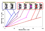
Fig. 1: Aggressive intensity of cavitating jet using various nozzle
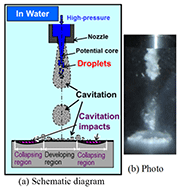
Fig. 2: Impinging submerged water jet
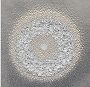
Fig. 3: Aspect of pure aluminum specimen exposed to submerged water jet
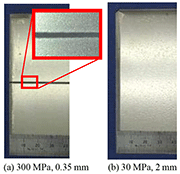
Fig. 4: Aspect of stainless steel scanned by submerged water jet
(1)
(2)
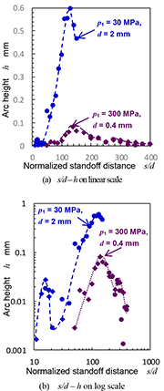
Fig. 5: 1st and 2nd peak on relationship between standoff distance and aggressive intensity of submerged water jet
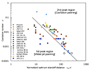
Fig. 6: Illustration of the classification map for cavitation peening and water jet peening
Introduction
Although typical mechanical surface is shot peening, peening methods without shots using a high-speed water jet have been proposed. In the case of peening methods using the water jet, there are two types of mechanism. One of them is called "water jet peening". In water jet peening, impacts of droplets [1-3] or shots [4-6], which are added in the jet, are utilized. The other is "cavitation peening" [7-10], in which cavitation impacts around the jet are used.
As mechanisms of the peening are different, optimum condition for each peening is totally different. A high injection pressure is required for water jet peening such as 200 or 600 MPa [11]. However, relatively low injection pressure such as several dozen MPa with large nozzles is suitable for cavitation peening [12]. In addition, the suitable geometry of nozzle for cavitation peening is different from the nozzle for water jet peening. Figure 1 illustrates mass loss induced by an impinging cavitating jet as a function of test time for various nozzles [13]. In Fig. 1, aggressive intensity of the jet was demonstrated by the mass loss; namely, larger mass loss means larger aggressive intensity of the jet. Note that there is no damage at cavitation peening, as the process is finished before damage is produced. As shown in Fig. 1, the aggressive intensity of the suitable nozzle for the cavitating jet is 6 times larger than that of a conventional nozzle for the water jet.
In the present paper, the basis for classification between cavitation peening and water jet peening was proposed in order to optimize each peening condition. Note that appellations of "water jet peening" and "cavitation peening" are used instead of colloquial terms, following the mechanism of impacts in order to avoid misunderstanding of the peening mechanism [14].
Cavitation Peening and Water Jet Peening Using a Submerged Water Jet
As mentioned above, impacts induced by the collision of water droplets and/or shots which are added in the water jet are used in water jet peening. In the case of cavitation peening, impacts induced by cavitation bubble collapses are used. When the water jet is injecting in air, it is easy to distinguish water jet peening and cavitation peening, as cavitation bubbles are not produced excepting a special jet. The special jet means that Soyama developed a cavitating jet in air by injecting a high-speed water jet into a low-speed water jet, which is injected into air using a concentric nozzle [15, 16].
Misunderstanding normally happens in a usage of a submerged high-speed water jet, i.e., a high-speed water jet in water. As shown in Fig. 2, cavitation was produced in the nozzle and/or in shear layer around the jet and was combined together, then spread out as a ring cavitation on impinging surface. As cavitation collapses, impacts are produced. This is why a ring pattern is observed by impinging of a cavitating jet (see Fig. 3). In order to reveal treatment area by the submerged water jet, Fig. 3 shows the aspect of a pure aluminum specimen exposed by the submerged water jet whose injection pressure was 30 MPa. As mentioned above, a typical erosion pattern can be seen in Fig. 3; furthermore, the jet center was eroded and this erosion at jet center was produced by the droplet impacts of jet center. Namely, the droplet impacts exist even through a submerged water jet of injection pressure of 30 MPa.
As expected, when the injection pressure of the jet is increased, the damage induced by the droplets is more remarkable. Figure 4 reveals aspect of the surface of stainless steel SUS316L scanned by the submerged cavitating jet. In Fig. 4 (a), the injection pressure of the jet was 300 MPa using a nozzle of 0.35 mm in diameter. On the other hand, the injection pressure of 30 MPa with 2 mm diameter nozzle was used in Fig. 4 (b). Both jet power, which was defined by the flow rate and the injection pressure were nearly equal. In the case of 300 MPa, the damage was observed at the jet center, and in the case of 30 MPa, the plastic deformation pits were produced without damage. Note that the introduced compressive residual stress of 30 MPa was larger and deeper than that of 300 MPa [17]. Namely, in the case of cavitation peening, the cavitating jet of relatively low injection pressure with large nozzle is suitable compared with the jet of high injection pressure with small nozzle.
On the other hand, in the case of water jet peening, high injection pressure is required to accelerate droplets and/or shots in the jet. Thus, it is very important to distinguish whether cavitation peening or water jet peening was used.
Aggressive Intensity of Submerged Water Jet as a Function of Standoff Distance
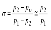
In order to demonstrate the aggressive intensity of the submerged high-speed water jet, Fig. 5 illustrates the arc height of spring steel treated by the jet as a function of standoff distance normalized by the nozzle throat diameter d [18]. As the value of arc height was varied, the arc height was plotted on the log scale in Fig. 5 (b). As the relationship between cavitation number ? and optimum standoff distance sopt can be plotted on the straight line on log-log scale [19], the vertical axis is also described on log scale in Fig. 5 (b). Here, the cavitation number ? was defined by the injection pressure p1, pressure at nozzle outlet p2 and vapor pressure pv as shown in Eq. (1).
(1)
The s was simplified as Eq. (1), because of p1 >> p2 >> pv.
In Fig. 5, the thickness of the spring steel was 1mm and the Vickers hardness was 535 ± 14. The processing speed was 1 mm/s.
For both cases, there are two peaks: 1st peak and 2nd peak, changing with standoff distance at s/d = 16 and 131 of p1 = 30 MPa, and s/d = 137.5 and 275 of p1 = 300 MPa. The maximum values of arc height were 0.596 mm at s/d = 131 for p1 = 30 MPa and 0.0825 mm at s/d = 137.5 for p1 = 300 MPa respectively. Namely, the aggressive intensity of p1 = 30 MPa was 7 times larger than that of p1 = 300 MPa. Although the standoff distances at both peaks were similar s/d, the mechanisms of the aggressive intensity were different. Because the cavitation numbers at each case were ? = 0.0033 at p1 = 30 MPa and ? = 0.00033 at p1 = 300 MPa, the optimum standoff distance due to cavitation impacts was increased with a decrease of cavitation number [19]; Thus, the peaks at s/d = 16 of p1 = 30 MPa and s/d = 137.5 of 300 MPa were induced by impacts of the water droplets. On the other hand, the peaks at s/d = 131 of p1 = 30 MPa and s/d = 275 of p1 = 300 MPa resulted from the cavitation impacts. The above-mentioned mechanisms of each peaks are discussed in the following section including the results reported by other researchers.
Classification Map for Cavitation Peening and Water Jet Peening
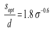
Figure 6 illustrates the classification map for cavitation peening and water jet peening. The position of standoff distances that was normalized by nozzle diameter at each peak is plotted in Fig. 6. The following line to distinguish between cavitation peening and water jet peening is also revealed in Fig. 6 [14].
(2)
The text in Fig. 6 shows the abbreviated name of the journals in which results were reported. The detail is described in the references [18]. In Fig. 6, the number of the data was 127 points including the above-mentioned 4 points. Some plots overlap, as similar nozzles were used.
In Fig. 6, the left lower region of the line of Eq. (2) is the water jet peening region, in which the droplet impacts result in the 1st peak. On the other hand, the right upper region of the line is the cavitation peening region, in which the cavitation impacts produce the 2nd peak.
The peak at s/d = 137.5 of p1 = 300 MPa (? = 0.00033) is obviously located within the water jet peening region, and the peak at s/d = 275 of p1 = 300 MPa is plotted within the cavitation peening region. In the case of water jet peening, peening ability increases with increase of injection pressure. However, in the case of cavitation peening, too high an injection pressure produces not only less peening effect but also damage due to impinging of the droplet impacts at the jet center [17]. This is why distinguishing between water jet peening and cavitation peening to obtain better peening effect avoids such damage.
As mentioned above, the arc height had a maximum at s/d = 131 of p1 = 30 MPa. The jet of a relatively low injection pressure with large nozzle produces better peening effect.
Conclusions
In order to get better peening effect by using a submerged water jet, a classification map to distinguish between cavitation peening and water jet peening is proposed. Cavitation peening and water jet peening can be classified by considering the cavitation number and standoff distance from the nozzle to the target.
Acknowledgement
This work was partly supported by JSPS KAKENHI Grant Number 24360040. The author thanks Mr. M. Mikami, technician, Tohoku University for his help with the experiment.
References
[1] K. Enomoto, K. Hirano, M. Mochizuki et al., "Improvement of residual stress on material surface by water jet peening," Journal of Society of Materials Society, Japan, vol. 45, no. 7, pp. 734-739, 1996.
[2] S. R. Daniewicz, and S. D. Cummings, "Characterization of a water peening process," Journal of Engineering Materials and Technology-Transactions of the Asme, vol. 121, no. 3, pp. 336-340, Jul, 1999.
[3] A. S. Grinspan, and R. Gnanamoorthy, "A novel surface modification technique for the introduction of compressive residual stress and preliminary studies on Al alloy AA6063," Surface & Coatings Technology, vol. 201, no. 3-4, pp. 1768-1775, Oct, 2006.
[4] Y. Yoshioka, "High-grade process of engine parts treated by water jet peening," Machine and Tool, vol. 46, no. 10, pp. 25-29, 2002.
[5] B. Sadasivam, A. Hizal, and D. Arola, "Abrasive waterjet peening with elastic prestress: A parametric evaluation," International Journal of Machine Tools & Manufacture, vol. 49, no. 2, pp. 134-141, Feb, 2009.
[6] A. Naito, O. Takakuwa, and H. Soyama, "Development of peening technique using recirculating shot accelerated by water jet," Materials Science and Technology, vol. 28, no. 2, pp. 234-239, 2012.
[7] H. Soyama, K. Saito, and M. Saka, "Improvement of Fatigue Strength of Aluminum Alloy by Cavitation Shotless Peening," Journal of Engineering Materials and Technology, vol. 124, no. 2, pp. 135-139, 2002.
[8] H. Soyama, "Improvement of fatigue strength by using cavitating jets in air and water," Journal of Materials Science, vol. 42, no. 16, pp. 6638-6641, 2007.
[9] H. Soyama, and Y. Sekine, "Sustainable Surface Modification Using Cavitation Impact for Enhancing Fatigue Strength Demonstrated by a Power Circulating-Type Gear Tester," International Journal of Sustainable Engineering, vol. 3, no. 1, pp. 25-32, 2010.
[10] H. Soyama, "The Use of Cavitation Peening to Increase the Fatigue Strength of Duralumin Plates Containing Fastener Holes," Materials Sciences and Applications, vol. 5, no. 6, pp. 430-440, 2014.
[11] A. Chillman, M. Ramulu, and M. Hashish, "Waterjet peening and surface preparation at 600 MPa: A preliminary experimental study," Journal of Fluids Engineering-Transactions of the Asme, vol. 129, no. 4, pp. 485-490, Apr, 2007.
[12] H. Soyama, K. Nagasaka, O. Takakuwa et al., "Optimum injection pressure of a cavitating jet for introducing compressive residual stress into stainless steel," Journal of Power and Energy Systems, vol. 6, no. 2, pp. 63-75, 2012.
[13] H. Soyama, "Effect of nozzle geometry on a standard cavitation erosion test using a cavitating jet," Wear, vol. 297, no. 1-2, pp. 895-902, 2013.
[14] H. Soyama, "Surface Mechanics Design of Metallic Materials on Mechanical Surface Treatments" Mechanical Engineering Reviews, vol. 2, no. 1, pp. 14_00192_1-20, 2015.
[15] H. Soyama, "Introduction of Compressive Residual Stress Using a Cavitating Jet in Air," Journal of Engineering Materials and Technology, vol. 126, no. 1, pp. 123-128, 2004.
[16] H. Soyama, 'High-Speed Observation of a Cavitating Jet in Air," Journal of Fluids Engineering, vol. 127, no. 6, pp. 1095-1108, 2005.
[17] H. Soyama, and O. Takakuwa, "Enhancing the Aggressive Strength of a Cavitating Jet and Its Practical Application," Journal of Fluid Science and Technology, vol. 6, no. 4, pp. 510-521, 2011.
[18] H. Soyama, "Criterion on mechanical surface treatment using a submerged water jet between cavitation peening and water jet peening," Jet Flow Engineering, vol. 31, no. 2, pp. 1-8, 2015.
[19] H. Soyama, and A. Lichtarowicz, "Cavitating Jets - Similarity Correlations," Jet Flow Engineering, vol. 13, no. 2, pp. 9-19, 1996.
Department of Nanomechanics
Tohoku University
6-6-01 Aoba, Aramaki, Aoba-ku, Sendai
980-8579, Japan
E-mail: soyama@mm.mech.tohoku.ac.jp


