E-Archive
Science Update
in Vol. 18 - May Issue - Year 2017
Shot Peening Media As Critical Parameter For Peening Aluminium Alloys

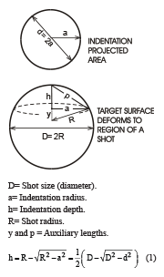
Table 1: Influence of the hardness of two aluminium alloys on the plastic deformation from three different shot sizes, defined in terms of the indentation radius (a) to the shot size (D) and its corresponding depth (h). This latter parameter was determined by using Fig. 1 and Eq. 1. It should be noted that the indentation radius was measured after only one pass of the peening stream on particular coupons (designed exclusively for this purpose). The coverage in this case is less than 100% coverage.

Figure 1: Schematic of a spherical sector, which represents a shot and the corresponding indentation area

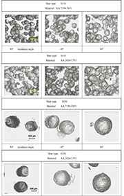
Figure 2: Images of the indentation shape and sizes left after peening the dedicated specimens for coverage measurements

Figure 3: Distributions for the S110 shot in terms of (a) its Feret’s diameter, (b) shape factor expressed as roundness and (c) aspect ratio in terms of the proportion between the major vs. the minor lengths of each measured shot

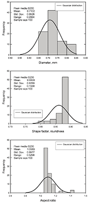
Figure 4: Distributions for the S230 shot, in terms of (a) its Feret’s diameter, b) shape factor expressed as roundness and c) aspect ratio in terms of the proportion between the major vs. the minor lengths of each measured shot

Table 2: Specifications of the peen media

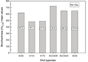
Figure 5: Micro-hardness Vickers of the as-received peen media
Introduction
The Shot Peening (SP) process has for some time been described as an effective mechanical surface treatment in tackling fatigue failure. This method is a cold working process that involves bombarding a metal component with a stream of small and relatively hard shot to induce desirable residual compressive stresses and strains within the surface layers of the component. The process was initially used in the automotive industry, but is now extensively used in the aerospace industry, not only to condition the metal surface of aircraft components, but also for producing curvature in panels. This process requires no dedicated tooling to achieve a given component shape, and can achieve large residual strains. Due to induced compressive stresses on the surfaces, the fatigue life of components is enhanced, which is the opposite effect of most other forming processes. A shot peening condition can be defined by such variables as: a) Shot, b) Incidence angle, c) Intensity, d) Saturation, e) Velocity and f) Coverage. SP produces changes to the target material, including modifications to microstructure, and topography and the creation of a compressive residual stress.
Some of these changes are beneficial, but some can be significantly detrimental. These opposite effects are often difficult to understand and poorly related to the peening conditions. Thus, the balancing between beneficial and detrimental effects makes it difficult to be certain regarding the peening behaviour and its impact on fatigue performance. In general, one can speculate that peening conditions for optimum fatigue strength should result from a surface hardening as high as possible, compressive residual stresses as large as possible, with a penetration as deep as possible, and with a surface roughness as low as possible. Compromises have to be made, however, (due to the complex interaction) to attain these final conditions. However, in the case of Aluminium alloys, they are more likely to be roughness-sensitive or surface damage-sensitive. Therefore, a note on peening media is worth studying to ensure better results in terms of fatigue resistance.
Shot peening media
The consistent degradation of fatigue life caused by peening media may be due to one or more of these factors:
1. Broken or highly deformed media and embedded particles, which give rise to deeper surface penetration (table1) and hence, more likely to cause crack nucleation by stress concentration.
2. Unevenness in the plastic deformation layer, 100% coverage with the finest shot is entirely impinged with some overlapping. Variations of the plastically deformed layer when peening with larger media size may be quantitatively greater than with smaller media.
3. The tendency of a larger media is to leave larger indentations and, thus, material around the indentation is displaced by a greater distance and would indent to a greater depth and or induce impact extrusion of material parallel to the surface. It has been reported by many researchers that such surface damage known as peened surface extrusion folds (PSEF) or simply folds are responsible for acceleration of the crack nucleation by the stress concentration.
The indentation radius a of each type of shot and at three different incidence angles for the two aluminium alloys under study was measured by using the image analysis system. It should be noted that the observed indentations were not perfectly spherical craters. Most were irregular in shape, being elongated, particularly for 45° and 30° incidence angles, (see Fig. 2). This indicated that, cutting and sliding effects took place during the impact; therefore, the minimum diameter was used for d as being more representative of the shot contact with the surface.
Considering that a critical parameter of the peening process is the shot itself, the shot media was sampled and graded at the beginning of the tests to ensure that shot quality met both MIL-S- and SAE requirements, and to observe whether there was any significant variation. The shot characteristics evaluated were those previously identified by Gillespie [1] and also specified by the relevant standards, namely:
i. Size (diameter).
ii. Shape factor (roundness).
iii. Aspect ratio (major length by minor length).
iv. Hardness (Hv).
v. Density.
There are three techniques, which either separated or combined, allow these geometric features to be determined [2-4]:
i) Visual inspection.
ii) Sieve analysis.
iii) Image analysis.
It has been reported that the image analysis (IA) technique allows the measurement of several features of as many individual shot particles as required, with highly descriptive and accurate results, which can be then statistically processed. Conversely, sieve analysis and visual inspection are neither as descriptive nor as accurate as IA. Taking into account the above considerations, the IA technique was adopted for characterising the size, shape factor and aspect ratio of the peen media used in this study. Samples of as-received shots were selected randomly by repeat sub-division of a tray of shots until approximately 100 remained as a non-biased sample, in accordance with British Aerospace (Airbus) specifications. A PC-based image analyser software (SigmaScan Pro ver. 5.0 Copyright © SPSS Inc.) and an optical microscope Olympus CH-2 LECO were employed for measuring purposes. The geometric features that were measured on a two-dimensional plane are defined as follows:
1) Size in terms of the shot diameter: calculated as the Feret’s diameter, which is the diameter of a fictitious circle that has the same area as the shot being measured, given by ?.
2) Shape factor: a measure of a shot’s circularity, which is given by ?.
A perfect circle has a shape factor of 1. Unacceptably shaped shots have a roundness of less than 0.81.
3) Aspect ratio: a proportion between the major lengths over the minor lengths. Acceptable values range between 1 and 1.2.
Figs. 3 (a-c), show the distributions of size, shape factor and aspect ratio of the S110 shot respectively.
From Figs. 3, it can be seen that whilst the shape factor and aspect ratio distributions give acceptable values, i.e., the shot was mostly round; the distribution of the shot size presents a significant variability in relation to the nominal diameter, i.e., the shot size ranges between 0. 30 to 0.38 mm. In Figs. 4 a-c, the statistical behaviour of the shot S230 is illustrated.
Similar behaviour was observed for the shot S230 (Fig. 4 (a-c)); namely, the distributions of the shape factor and aspect ratio each have acceptable values compared with Table 2, whereas the distribution of the diameter indicates the mean values to be well above the nominal diameter.
Regarding the shot sizes, it was found that there is no clear definition of the tolerances. Significant differences between specifications are reported. For example, whilst the dimensions of the S110 and S230 shots are consistent with MIL-S-13165C [6] specifications, these same magnitudes exceed the tolerances observed by SAE-HS84 [5].
Based on the recommendation that for an optimum compressive residual stress (magnitude and depth), peen media should be at least as hard as the part being peened, hardness of the shot was measured.
In accordance with [7], a sample of approximately 50 shot was mounted in epoxy resin cured below 140 °C and polished to approximately the centre of the shot using a water-flushed rotary metallographic grinder with an initial 400 grade silicon carbide (SiC) paper and progressively using finer abrasives until a 1200 grade grit paper was reached, followed by diamond paste with a grain size of 1 µm. The micro-hardness of 20 of these shots was measured in the centre of the polished area of each shot using a Matsuzawa Seiki Micro-hardness Tester with a 500 g load and a hold-down time of 10 seconds. The Vickers indenter made diamond-shaped impressions, the sizes of which were measured to an accuracy of 0.1µm. The average of twenty micro-hardness measurements per shot is shown in Fig. 5.
The evaluated micro-hardness was found to be consistent with the specifications. Minor deviations were observed in the whole batch examined. Shot types S110 and S170 were softer than S330, S230 and the CCW20 types.
Final remarks
There is a clear proportionality between the size of the shot and the roughness of the peened surface, i.e. the larger the shot the deeper the impact, as observed in Table 1. This latter observation leads to the assertion that stress concentration is shape- and not size-dependent, although notch sensitivity may be size-dependent. In light of the above observations, the highest stress concentration values were found on the peened coupons with the shot type SCCW20. To this end, the shot geometric features previously determined revealed that the highest scatter in roundness and aspect ratio distributions were exhibited by this type of shot. Furthermore, the surface that was peened with this kind of shot was found to consist largely of sharp peening indentations; namely, deep penetration with narrow dents. These findings support the observation made earlier concerning the dependence of indentation shape on the stress concentration factor.
References
1. Gillespie, R.D., (1993), "Shot peening media: Its effect on process consistency and resultant improvement in fatigue characteristics." In: The Fifth International Conference on Shot Peening (ICSP-5). Oxford, UK. Ed. David Kirk. Coventry University: pp. 81-90.
2. British Aerospace (operations), limited, 1997, "Shot peening for improved fatigue and stress corrosion resistance. British Aerospace (Airbus), PROCESS SPECIFICATION (ABP 1-2031)": England, UK. pp. 1-23.
3. Bohn, Per, (1993), "The control of the shot peening media by sieve analysis." In: The Fifth International Conference on Shot Peening (ICSP-5). Oxford, UK. Ed. David Kirk. Coventry University: pp. 91-98.
4. British Aerospace, PLC, 1993, "Determination of the shot peening and blasting intensity by Almen gauge. British Aerospace (Airbus), PROCESS SPECIFICATION (ABM 1-2031)": England, UK. pp. 1-11.
5. Committee, SAE Fatigue Design and Evaluation, (1991), SAE Manual on Shot Peening (SAE HS-84). 3rd ed. Society of Automotive Engineers, Inc.: pp. 19-20.
6. Military Specification, MIL-S-13165C, 7 June1989, "Shot peening of metal parts". The Wheelabrator Corporation: USA.
7. British Aerospace PLC, 1994, 1995, "Carbon steel spherically conditioned cut wire for shot peening. British Aerospace (Airbus), PROCESS SPECIFICATION (ABM 9-9076)": England, UK. pp. 1-7.
Public Education Secretary of Mexico
Instituto Tecnológico de Tlalnepantla del TecNM
Postgraduate Office/Department of Mechanical Engineering
E-mail: josesolis@infinitum.com.mx


