


E-Archive
Articles
in Vol. 4 - September Issue - Year 2003
Blasting, Peening, and Finishing Efficiencies Rely on Proper Nozzle Selection
Author: Herb Tobben, Manager, Sample Processing Laboratory ZERO Blast Cabinets and Automation, Clemco Industries Corp., Washington MO USA
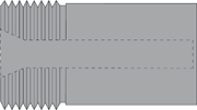
Straight-Barrel Nozzle
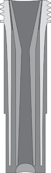
Venturi Nozzle
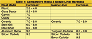
Shows the relative hardness on the Mohs

Shows the relative life expectancy for the three most popular nozzle liner materials with steel media

Clemco Industries Corp. manufacturers automated blast cabinets, blast rooms, blast cabinets, portable blast machines, and a complete line of nozzles and other blast components. The company has a worldwide network of licensees, subsidiaries, and distributors.
To speed production and to ensure conformity to specification, most companies with high volume parts processing requirements choose automated blasting. An automated blasting, peening, or finishing operation offers consistent, repeatable results. Repeatability is the value proposition in a successful operation.
Achieving repeatability depends upon delivering a uniform quantity of media at a consistent velocity and striking the target surface area in the same way each and every time. Whether or not results are monitored and measured, as they need to be with shot peening, the operation for blast cleaning and finishing applications demands similar adherence to proper procedure for the best results.
Pressure blasting is chosen for some high-production air-powered processes because it propels media at a higher velocity through the blast nozzle than suction blasting. In air-powered pressure blasting, media feeds from a pressure vessel into a moving stream of compressed air through a metering valve, blast hose, and nozzle.
Perhaps the most critical component for reaching production goals is the nozzle chosen for the job. With the help of its internal shape, the nozzle distributes the media as needed for the application. Two types of pressure blast nozzles are generally used. They are designed with unique internal shapes to achieve different objectives. Both types have a broad entry area, which sharply tapers to an orifice—the smallest inside diameter (ID) of the nozzle and, in fact, the smallest area in the entire blast system. The rapid reduction in ID and the controlled expansion of the compressed air, moving through the nozzle, work together to accelerate the media toward their target.
As its name indicates, a straight-barrel nozzle has a straight, constant-diameter barrel, the point between the orifice and the exit-end of the nozzle. When the air and media reach the nozzle exit, the less-dense air quickly expands once the influence of the nozzle barrel is absent, and momentum carries the media along the center of the blast pattern. The straight-barrel shape creates a relatively small blast pattern with a very high intensity tapering out to lower impact at the perimeter. While it takes longer to cover a large surface area with such a small hot spot of higher intensity compared with other nozzle shapes, the straight-barrel shape works well in recessed or restricted areas.
Unlike the straight-barrel nozzle, the venturi nozzle gradually tapers outward from the orifice to the exit-end of the nozzle. This gradual exit expansion allows a mixing of air and media within the nozzle causing them to expand uniformly before leaving the nozzle. A venturi nozzle provides excellent peening intensity and cleaning capability with a broad pattern. The performance of the venturi nozzle depends on a precise ratio of length to orifice size, and to entry and exit tapers. This design creates a large blast pattern that produces uniform peening intensity and maximum acceleration for cleaning.
As nozzles wear from continuous exposure to high-velocity media, more air and media are allowed to pass through the orifice. The resulting larger area within the nozzle consumes more air volume placing greater demand on the compressed air source. Unless air volume can keep up with the increased flow, pressure at the nozzle will drop. With reduced pressure, peening intensity and productivity fall, and efficiency suffers. A rule of thumb to follow for ensuring continuous high production is to replace the nozzle when the orifice wears to the next larger size. Generally, that means 1/16” or 1.5 mm. In the USA, nozzle sizes are measured in 1/16” increments. A No. 6 nozzle has an orifice of 6/16” (3/8”); the next larger size is No. 7 with an orifice of 7/16” (11 mm). In Europe and elsewhere, nozzle sizes are indicated in millimeters.
The relative life expectancy of a nozzle depends upon the combination of liner material and abrasive/media. The harder the media, the more durable the liner material must be to withstand exposure to it over an acceptable life. A commonly employed industry reference is the Mohs’ scale, which offers a method of measuring relative hardness, on a scale from 1 to 10, in non-metallic media and nozzle liner materials. Metallic media (steel) is measured on the Rockwell scale. Common steel media range from soft Rc-35 to hard Rc-65.
As critical as are the choices of nozzle shape and liner material, distance between the nozzle and the target object greatly affects the overall productivity of the blast cleaning, finishing, and peening processes. For efficiency in cleaning and finishing, and to adhere to strict peening intensity specifications, the target area must be covered with precision. Overlapping coverage wastes valuable resources in cleaning and finishing, and may not produce specified results in peening applications. With the relatively larger pattern produced by the venturi nozzle, it is important to be able to calculate the area the blast will cover.
Calculating the blast pattern size is easy; simply multiply 0.125 times the distance between its exit end and the target surface, and add the ID size of the nozzle orifice. For example: the pattern size produced by a 3/8“ (9.5mm) nozzle positioned 8 inches (203.2 mm) from the surface is 1.375 inches (34.9mm).
Once calculated, the area covered by the chosen nozzle(s) is determined, leading to further decisions regarding precisely what system configuration (i.e. number of nozzles needed) will do the job in the desired timeframe and within the defined budget.
For information:
Clemco Industries Corp.
One Cable Car Drive, Washington
Mo 63090, USA
Tel: +1.636.239 0300
Fax: +1.636.239.0788
E-mail: info@clemcoindustries.com
www.clemcoindustries.com