Introduction
Laser-cladding (LC) is one of the direct energy deposition (DED) methods for additive manufacturing of metallic components with reduced cost. From the application point of view, it can be applied for homogeneous deposition, i.e., depositing the same alloys as the workpiece, e.g., to repair damaged turbine blades. It can also be applied to deposit high alloys heterogeneously on low alloys for protective coating. Recent reports show that the repair of individual inconel 713 and stainless steel SS321 turbine blades by LC to replace new ones can save the cost by over 75% and 65%, respectively. Driven by the remarkable cost-efficiency, LC technique has been attracting increasing research interest [1]. Pore- and crack-free LC alloys, e.g., Ni-based superalloys, are readily entering into practical applications.
Different from traditional arc welding, LC is using laser as the heating source to melt the powder and/or wire source materials fed into the melt pool (MP) and fuse them into the surface of the workpiece. Compared with arc welding, the laser heating gives rise to more rapid temperature changes at the vicinal regions of the MPs. As a result, cracking is frequently observed at the MP centers after solidification upon improper LC parameters. Recent studies have revealed that the LC parameters for Ti-alloy are more critical than those for Ni- and Fe-based alloys owing, to the high reactivity of Ti, especially when processing in open environments where oxidation reactions might occur even under argon-shielding.
Along with the LC development, the effect of LC on the substrate or the deposited alloy, especially at the near-interface areas, has also been attracting research interest. For example, to interrupt the epitaxial grain growth from the deposited layer into its following layer, machine hammer peening has been introduced following the individual Ti-alloy layers deposited by LC [2]. Such an inter-pass cold-working process tends to reduce the β-grain epitaxy from centimeters to 1~2 mm that might, in turn, improve the fatigue life of the Ti-alloy. The tensile strength of the LC-deposited Ti-alloy has also been improved by the incorporation of the inter-pass cold-working. In comparison with the homogeneous deposition, the effect of LC on the heat-affected zone (HAZ) induced in the substrate becomes more important when processing heterogeneous LC depositions, e.g., the protective coatings on low-alloy steel substrates.
We have recently studied LC-deposition of Ni- and Fe-based high alloys, i.e., In625 superalloy and SS431, on high-strength low-alloy steel (HSAS4140) substrate for corrosion protections. The former is typically used for high-temperature applications [3-4], e.g., on the water-wall of incineration plants, while the latter has wide applications at room temperature, including those of the chemical, petrochemical, and oil and gas industries, as well as general urban infrastructure, e.g., underground pipeline and rebar structures, etc. HAZ has been observed in the HSAS4140 substrate with different thicknesses for the LC-In625 and LC-SS431 processes using the same parameters. Here, we present a brief update on the morphological, structural, and mechanical characterizations of the LC-induced interface and HAZ, addressing their importance in protective coatings.
Material and Methods
The chemical compositions of the HSAS4140 substrate and the In625 and SS431 feedstock powders have been summarized in Table 1. The particle size distributions of the powder feedstocks are also tabulated from comparisons.
The surface of the substrate (60 mm X 60 mm squared plates of 20 mm thick) was polished and then cleaned using acetone wipes before the LC-deposition. For the SS431 deposition, the curved surface of the substrate was also used by machining grooves with the curvature radius of 6-20 mm. In this case, the LC was processed along the groove length directions. LDM 4000-100 laser was used as the energy source, which was guided through optical fiber with the optical window at λ = 1000 nm and the numerical aperture of 0.2. The Coax-8 nozzle was applied with the OTZ-5 (Laserline) optical setup. The laser beam was aligned along the surface normal direction of the substrate and the spot diameter on the surface was 4.0 mm. The cladding head was fixed on a 6-axis robot platform. The source powders were carried by pure argon (99.995%) and fed through an AT-1210 (Thermach) powder feeder. Pure argon was also used as the shielding gas during the LC-process. The LC parameters are the same for both the In625 and SS431 depositions; they include the laser power of 2200 W, cladding velocity of 1200 mm/min, and the powder-feeding rate of 30 g/min.
Morphological, structural, and mechanical properties of the LC-deposited coatings, especially the HAZ induced in the HSAS substrate, have been studied by employing optical microscopy, X-ray fluorescence (XRF), and nanoindentation techniques. They, together with the chemical etching and material removal from the cross-sections, provide evidence that the HAZ might form the pain-point and should be specially treated in LC-deposition of protection coatings.
Results and Discussion
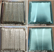
Figures 1(a) and 1(b) present the typical photographs taken from the LC-In625 coatings before and after grinding respectively. Likewise, those taken from the LC-SS431 coatings are presented in Figs. 1(c) and 1(d). The general visualization reveals an absence of any structural defects, e.g., cracks, voids, etc., for both coatings. The absence of structural defects within the LC-deposited In625 and SS431 coatings has also been confirmed by employing visible dye penetrant testing.
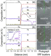
Figures 2(a) and 2(b) present the composition profiles measured by XRF from the cross-sections across the interfaces of the LC-In625/HSAS4140 and LC-SS431/HSAS4140 respectively. Likewise, the photographs taken from the cross-sections are presented in Figs. 2(c) and 2(d) respectively. The cross-sections were made perpendicular to the longitudinal directions of the LC scanning tracks, which clearly exhibit the interface, the HAZ in the substrate adjacent to the interface, and the inter-pass boundaries of the LC-deposited coatings. The morphological comparisons between the LC-In625/HSAS4140 and LC-SS431/HSAS4140 show that (i) the coatings have distinct MPs, the In625 MPs are narrower and thicker than those of SS431; (ii) surface melting of the substrate occurred in the LC-In625 [see the arrow in Fig. 2(c)] rather than in the LC-SS431 deposition; and (iii) the HAZ induced in the HSAS4140 substrate by the LC-In625 deposition is thicker than that induced by the LC-SS431 deposition. These observations suggest that the highest temperatures were higher during the LC-deposition of In625 than that of SS431. The most possible reason could be that the thermal conductivity of SS431 (~20 Wm-1K-1) is higher than that of In625 (~9.8 Wm-1K-1). Another reason is related to the MP shapes. The SS431 MPs are broader and thinner than the In625 ones, which lead to larger contact areas with the substrate and thus a better heat dissipation efficiency.
The composition profiles in Fig. 2(a) show apparent substrate dilutions in the LC-In625 deposition, where Fe diffused deeply into the MPs of the first layer. In comparison, the substrate dilution is minor in the LC-deposition of SS431 [see Fig. 2(b)]. This comparison is consistent with the higher temperature of the In625 MPs than that of the SS431 MPs during the LC-deposition. The inset in Fig. 2(b) presents a more detailed comparison between the Cr compositions across the interfaces of the LC-In625 and LC-SS431 coatings on HSAS4140. The interface region of the LC-In625 on HSAS4140 is apparently wider than that of LC-SS431 on HSAS4140, which further supports the higher temperatures in the In625 MPs than those in the SS431 ones during the LC-deposition.
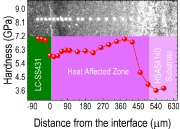
Figure 3 presents the hardness measured by nanoindentation from the cross section across the interface between the LC-SS431 coating and the HSAS4140 substrate. The inset is a microphotograph recorded after the nanoindentation measurements. One sees that the hardness of the SS431 coating in the vicinal regions of the interface, i.e., ~7.0 GPa, is significantly higher than that of the base material of the HSAS4140 substrate, i.e., ~3.6 GPa. Also seen is that the hardness is remarkably increased in the HAZ and such increase is non-uniform as a function of the distance from the interface. Since the XRF measurements revealed undistinguishable compositional variations in the HAZ, the hardness increment is attributable to microstructural changes, e.g., grain growth, non-tempered martensite, and carbide precipitations. These microstructures tend to promote corrosions, hydrogen embrittlement and cracking when exposed to aggressive environments and should be minimized, e.g., via post-LC treatment, in the HAZ [5].
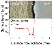
Figure 4 presents the surface heights measured from the cross-section of the LC-In625 coating on HSAS4140 substrate after chemical etching for 5 min in a mixture of 15 ml HCl (37%), 10 ml HNO3 (70%), and 10 ml CH3COOH (30%). The increased material removal from the HAZ as compared with that from the base material of the HSAS4140 substrate confirms the performance degradation of the HAZ. The height profile also validates the thickness of the HAZ, which, together with the chemical compositions shown in Fig. 2(a), confirms that the increased chemical etching rate at the HAZ is due predominantly to the microstructural changes.
Conclusion
In625 and SS431 coatings have been deposited by LC with the same parameters on HSAS4140 substrates respectively. Morphological, structural, and elemental characterizations across the coating/substrate interface revealed that the highest temperatures reached in the MPs of the In625 coating are higher than those of the SS431 coating, most likely being due to the lower thermal conductivity of In625 than that of SS431. The broader and thinner MPs of the SS431 coating than those of the In625 coating could also promote the heat dissipations. As a result, surface melting of the substrate along with substrate dilution occurred during the LC-deposition of In625 rather than SS431. The HAZ induced in the substrate is thicker for the LC-In625 than that for the LC-SS431 deposition. The hardness measurements and the chemical etching testing on the cross-sections across the interface and the HAZ provide evidence that microstructural changes, e.g., grain growth, non-tempered martensite, and carbide precipitations, tend to promote chemical corrosions. They should be mitigated during the LC-process or minimized via post-LC treatment in the HAZ for improved protective coatings.
Acknowledgement
This work is supported by A*STAR RIE2020 advanced manufacturing and engineering (AME) programmatic grant through the structural metal alloys program (SMAP, Grant no. A18B1b0061). The authors would also like to appreciate the technical support provided by Roy Lim and T. F. Wang from Dura-Metal (S) Pte. Ltd.
References
[1] H. Liu, et al., “Advanced surface engineering and protective coating” in Proceedings of the second International Conference on Advanced Surface Enhancement (INCASE 2021), Singapore, Y. Wei; S. Chng, Eds. Springer Singapore: Singapore, 2021; pp 138-141.
[2] L. Neto, et al., “Mechanical properties enhancement of additive manufactured Ti-6Al-4V by machine hammer peening” in Proceedings of the first International Conference on Advanced Surface Enhancement (INCASE 2019), Singapore, Itoh, S.; Shukla, S., Eds. Springer Singapore: Singapore, 2019; pp 121-132.
[3] H. Liu, et al., “Laser-cladding and interface evolutions of inconel 625 alloy on low alloy steel substrate upon heat and chemical treatments” Surf. Coat. Technol. Vol. 404, pp. 126606, 2020.
[4] H. Liu, et al., “Hot corrosion and internal spallation of laser-cladded inconel 625 superalloy coatings in molten sulfate salts” Corros. Sci. Vol. 193, pp. 109869, 2021.
[5] C.C. Silva, et al., “Evaluation of AISI 4140 steel repair without post-weld heat treatment. J. Mater. Eng. Perform. Vol. 18, pp. 324-331, 2009.
Hongfei Liu (Ph. D. in Physics)
Senior Scientist, Group Leader
E-mail: liuhf@imre.a-star.edu.sg
Chee Kiang Ivan Tan
(Ph. D. in Eng.)
Senior Scientist, Department Head
Institute of Materials Research and
Engineering (IMRE), A*STAR
(Agency for Science, Technology and
Research), 2 Fusionopolis Way,
Singapore 138634, Singapore


