E-Archive
Science Update
in Vol. 8 - May Issue - Year 2007
Stress Peening – a Practical Application: Minibloc-Springs

Prof. Dr. Eckehard M
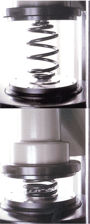
Fig. 1: The residual stress distribution (schematically) after the different steps
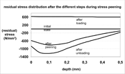
Fig. 2: A Minibloc-spring unloaded and loaded
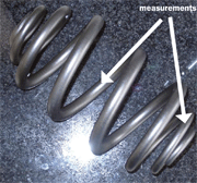
Fig. 3: The two points where the measurements were done
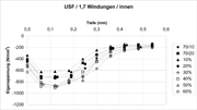
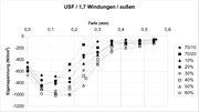
Fig 4a, b: Compressive residual stress profile at 1.7 coils
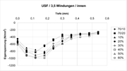
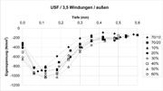
Fig. 5a, b: Compressive residual stress profile at 3.5 coils
1. Introduction
Today the reduction of weight or material is a current subject in wide areas of automotive and mechanical engineering. Several possibilities are available, like a better utilization of the material by higher hardness or optimizing the construction by finite elements. Another possibility is the induction of compressive residual stresses in the surface layers, especially used at tensile pulsating load to enlarge the dynamic life time or respectively reduce the weight. One possibility is stress (shot) peening, which is used at coil springs at the suspension of cars.
2. Basics
2.1 Stress Peening
Shot peening is a technology, which is a standard procedure. Peening (in the technical understanding) is the interaction between a particle (with the necessary hardness) with the surface of a working piece. If the particles have a round shape, you call it shot peening [Mü 94]. In the surface layer (up to 0.5 mm depth) compressive residual stresses are induced. At a lower hardness of the working piece an additional hardening is achieved. In order to obtain better results by the peening process, the so-called stress peening is used. Here the working piece or component is stressed in the direction of the later loading. After this step, the original peening procedure is done and afterwards the unloading. The compressive residual stress profile, which is now obtained, is significantly higher than that gained by normal peening (see fig. 1). The result depends on the (torsional-) preload (?ks) ?ks during peening [e.g.: Mü 93, Mü 94, Mü 96, Mü 97, Mü 06a, Mü 06b, Sc 05, Ze 93].
2.2 Basics Minibloc-Springs
The minibloc-spring is a special type of coil spring, which is established at the rear axis of many cars. Typical for a minibloc-spring are its small eyes, which are coiled with a wire of a small diameter. The wire diameter and the coil diameter increase continuously. In the middle of the spring there are respectively two coils, which have a constant wire and coil diameter as shown on the right picture.
When the spring is compressed, the coils do not touch each other, but most of the coils dive into the next one. Due to this fact, the spring works without any noise. Another advantage is that the spring has only a height of two or three wire diameters at the solid length. As a result of this small space of the component, the loading capacity of the car can be significantly enlarged.
The barrel shape is ideal to realize a strong progressive rate. (Sometimes linear rates, which are also possible, are used). That means the higher the load of the vehicle, the harder (higher rate) the spring will be. Such a spring gives an optimal comfort in riding. At bad road conditions a use of the rubber bumps (jounce) is extremely rare.
3. Application
To obtain a higher performance of the spring, there are two possibilities:
|
-Changing the material to achieve a higher hardness |
|
-Increasing the amount of the compressive residual stresses in the surface layer. |
One possibility concerning the second item is stress peening. In this case, the performance increase by stress peening will be reported. Since there is a complicated geometry at minibloc springs, the experiment has to show the optimal parameters.
Therefore, a typical minibloc spring was peened under different preloads:
|
peening time |
preload |
notation |
|
(sec) |
(% of max. load possible) |
|
|
10 |
0 |
70/10 |
|
20 |
0 |
70/20 |
|
20 |
10 |
10 % |
|
20 |
20 |
20 % |
|
20 |
30 |
30 % |
|
20 |
40 |
40 % |
|
20 |
50 |
50 % |
|
20 |
60 |
60 % |
After the stress peening, the residual stress profile was determined at the inner and outer side of the wire in the middle of the spring and at 1.7 coils away from the end (see fig. 3). These measurements were executed by x-ray diffraction. The residual stress values were obtained by using the sin²?-2?-method [e.g.: No 87]. The direction of the measurements were 45° to the wire axis. Due to the torsional load in this direction, the maximum load stress was expected. Because of stress peening in this direction, the compressive residual stresses will have the biggest amount.
To obtain the residual stresses under the surface, the material was removed electrolytically. In this way you can be sure that no additional residual stresses are induced. Every 60 µm depth the measurement was done to a depth of 540 µm.
4. Results
The two sections at the spring where the measurements were done are the critical ones. The middle part is loaded up to the solid length. In around 1.7 coils there is a section where the spring has a weak point concerning durability. If you load the spring, one gets a shadowing of the coils over the whole spring. This fact causes the intensity of stress peening at the inner sides of the coil to be lower than at the outer side.
One can see the typical compressive residual stress profile which can be achieved by the Hertzschen pressure (see fig. 4, 5). The maximum of the compressive residual stress is at a depth of around 0.15 mm. At a depth of 0.35 mm, there is a nearly constant level of the residual stress. This is due to the fact that the spring was set (plastified) before peening. This compressive residual stress level is higher at the inner side of the coils than at the outer side caused by the forming of the wire to a coil [Fi 87].
By increasing the load during peening, the compressive residual stresses will also increase up to a loading stress of 50% of the maximum possible load. A load up to 60 % does not result in a significant increase. At the inner side of coil 1.7, a decrease of 10 % of the load of the residual stresses can be observed due to the fact that this coil dives into another one and is extremely shadowed by other coils.
In figure 5, the equivalent situation in the middle of the spring is shown. The compressive residual stress level is slightly higher. In particular, the residual stress at the inner side of the coil is about 100 N/mm² higher in comparison with the inner side of 1.7 coils.
At the outer side, a higher stress level is also obtained. (The higher residual stress level at a depth of 0.5 mm is due to the fact that the presetting of the spring always results in higher levels at the inner side of the coil [Fi 87].)
5. Conclusions
Stress peening is also possible for springs with a sophisticated geometry. All coils were peened over the whole surface (inner and outer side) with a sufficient intensity. With this operation another step is performed to reduce the weight of the spring. In combination with a higher tensile strength of the material [Fi 95,WE 06,] a weight reduction of 30% is possible.
6. Acknowledgement
I would like to thank my colleagues Prof. Dr. Otto Benning (FH Bochum) and Mr Bernd Rhönisch of Ahle Federn (Germany) for their contributions to this project. It was financially supported by the AiF under the number 17 089 00.
7. References
Fi 87: Fischer F. u. Vondracek H.: Warmgeformte Federn, Hoesch Hohenlimburg AG, Hagen 1987
Fi 95: Fischer F.; Müller, E.; Wienand, J.: Weight-optimized spring elements for car axles,
Technische Mitteilungen Krupp 2/1995, pp 69, Krupp, Essen 1995
Mü 93: Müller E.: Some aspects of stress peening of coil springs for vehicle suspensions, Proceedings of the 5th Int. Conf. on Shot Peening, pp. 341, Conventry University (UK), 1993
Mü 94b: Müller, E: Stress Peening of Compressive Coil Springs; WIRE 44 (1994) 6, pp. 368 - 372
Mü 96: Müller E.: Die Ausbildung von Eigenspannungen an Torsionsproben beim Spannungsstrahlen, Mat.-wiss. u. Werkstofftech. 27, (1996), pp. 354.
Mü 97: Müller E.: Eigenspannungsabbau an spannungsgestrahlten Torsionsproben unter
dynamischer Belastung, Mat.-wiss. u. Werkstofftech. 28, (1997), pp.549.
Mü 06a Müller E.: Optimazation of shot peening for fatigue critical applications. In Baiker St. (edit.): Shot Peening, pp. 120, mfn publishing house, Wetzikon, 2006
Mü 06b: Müller E. et al.: Die Ausprägung von Druckeigenspannungen durch Spannungsstrahlen an Minibloc-Federn, VDI-Berichte Nr. 1972, pp 285, Düsseldorf 2006
No 87: Noyan I. C. u. J. B. Cohen: Residual Stress, Springer Verlag, New York, 1987
Sc 05: Schulze V.: Modern Mechanical Surface Treatment, Wiley-VCH, Weinheim 2005
We 06: Weiß H et al.. Eigenschaften von thermomechanisch behandeltem Federstahl für Schraubendruckfedern, VDI-Berichte Nr. 1972, pp 55, Düsseldorf 2006
Ze 93: Zeller R.: Influence of stress peening on residual stresses and fatigue limit, in Residual Stresses, pp 907, DGM-Verlag, Oberursel, 1993
Fachhochschule Bochum
FB Mechantronik & Maschinenbau
Lennershofstr. 140
44801 Bochum, Germany
E-Mail: eckehard.mueller@fh-bochum.de
www.fh-bochum.de/fb4/institute/werkstoff


