


E-Archive
Science Update
in Vol. 9 - March Issue - Year 2008
Effect Of The Shot Peening Process On The Surface Changes In The 2024-T351 Aluminium Alloys
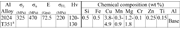
Table 1.: Materials: Mechanical properties and chemical composition
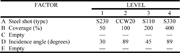
Table 3: Summary of shot peen factors evaluated by design of experiment
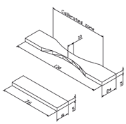
Figure 1: Dimensioned design drawings for the coupons and hourglass specimens (dimensions in mm).
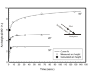
Figure 2: Example of peening intensity curves for 90, 45 and 30o incident angles. The saturation point is determined using the method described by equation (1). The material was Al 2024-T351.
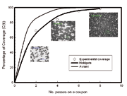
Figure 3: Experimental and theoretical coverage comparison of a coupon (Al2024-T351) with peening conditions: S230, 30? incidence angle and intensity of 19.3A (0.49 A mm)
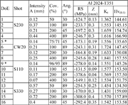
Table 4: Results of the designed of experiment analysis (conditions 1-16)
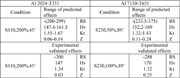
Table 5: Optimum shot peen conditions in terms of RS, Hv, Kt and Z
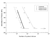
Figure 6: Effect of the peening process on the fatigue resistance of Al 2024-T351
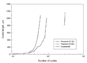
Figure 7: Crack growth comparison between peened and unpeened specimens of Al 2024-T351, tested at equivalent stress
Introduction
As shot peening alters the microstructure and properties of the peened layer, fatigue damage needs to be assessed in terms of Microstructural Fracture Mechanics. However, the magnitude of all these mechanical effects and the depth to which it extends beneath the surface of the component must firstly be controlled in order to obtain beneficial strengthening and to avoid introduction of severe damage (subsurface crack initiation and excessive roughness or stress concentration). It becomes immediately apparent that for shot peening to be consistently effective and reproducible, a number of parameters must be closely controlled. Among these, the most important are [1, 2]:
a) The treated component: geometry, material properties and monotonic and cyclic elastic-plastic behaviour.
b) The energy of the shot stream (intensity): properties of the shot, velocity, angle of incidence, offset distance, etc.
c) The percentage of indentation of the part surface (coverage): number of passes or duration of the treatment.
The object of this study is to obtain the best-peened properties of a component, through a characterization of the work hardening, surface stress concentration (roughness), residual stress and fatigue life, directly from the interaction of the process control parameters and initial component properties. Design of Experiments (DoE)/Robust Design methodology [3, 4] is applied in this study to optimise the surface treatment parameters and to find their optimum levels.
Experimental details
Materials and specimen preparation
This investigation focuses on the Aluminium alloys commonly used in aircraft structures, 2024-T351. The chemical composition and mechanical properties of the alloy are depicted in table 1. As this alloy was obtained in the form of rolled plate, it had a preferred grain orientation. The average grain size was as follows: 220 µm in the longitudinal direction, 80 µm in the transverse direction and 52 µm in the short transverse direction.
Two different specimen profiles were employed, one of them (coupon) for the assessing of the final peened material properties and another (hourglass) for the constant amplitude fatigue testing, as shown in Fig. 1. The dimensions of the coupons which were used to obtain the residual stresses, microhardness gradient and surface roughness were based on a thicker Almen strip “A” design so as to minimise the typical double deformation after peening as well as to avoid end effects. The hourglass-shaped specimens were used for the fatigue testing. The latter conform to standards for uniaxial fatigue test specimens (ASTM 466-82 and Airbus Industrie Test Method, AITM 1-0011). The surface roughness of the specimens before peening was Ra ? 0.7µm both for the coupons and for the calibrated gauge length (80 mm long) of the hourglass specimens.
The type/size of shot media used for the surface treatment is that of S330, S230, S110 and SCCW 20. These media were chosen because of their use by the aircraft industry.
Equipment and procedures
Peening conditions
The experimental peening equipment is that of the direct-pressure air blast type, fully described in [5]. To denote a shot peening condition, six parameters are used: Shot (type/size), Intensity, Incidence angle, Saturation, Coverage, and Velocity. These parameters are independent of the shot-peening machine utilised. It is clear that only shot type/size and incidence angle parameters are directly controlled. The remaining parameters are measured. Intensity and hence saturation, were therefore monitored using a standard digital type Almen gauge.
An equation in the following form, has been adopted for the intensity,
The formula can not be displayed online – ask for PDF (1)
Where A, b and p are fitting parameters. The output is the saturation point (time and arc height) shown in Fig. 2.
Coverage, expressed as a percentage of the dimpled area was experimentally obtained by using an image analysis system. Two theoretical models were assessed for the determination of coverage. One is a theoretical model reported by Kirk D et. al. [6] based on the Avrami approach
The formula can not be displayed online – ask for PDF (2)
Where r is the average radius of the indentations, A is the area of the shot spread, m represents the mass flow rate, ? is the average radius of the shot and ? is the shot’s density. The other was proposed by Holdgate [7] for predicting coverage in a general peening system,
The formula can not be displayed online – ask for PDF (3)
Where C(t + ?t) is the coverage after an increment of time, ?t; C(t) is the coverage at a known time t; ns is the number of peen sources; aj is the total area of indentation caused by the peens from the jth peen source at time ?t; S is the total area to be peened and ?Nj is the number of peens from the jth peen source expected to impact the reference area in an interval of time ?t. Comparison between experimental and theoretical outputs is given in Fig.3.
Bearing in mind the results achieved between the experimental and theoretical development of coverage, the Holdgate model was adopted in this study.
Design of experiments
One approach to studying the interaction effects between two or more factors in an experimental program is known as factorial design [8]. A total of three factors were evaluated at four levels, each as shown in table 3. A Taguchi L16(45) array was used to enable the optimisation of five parameters and each of these could be set at a maximum of four levels; the analysis with this array needs sixteen runs. The empty columns, third and fifth factors, were used to verify if all parameters influencing shot peening effects were considered. The evaluated effects are those obtained from the analysis of the residual stress/depth, from the observation of the microhardness/depth plots and from the stress concentration calculations, obtained from the direct roughness measurements. In order to evaluate these effects, the parameter MSD (mean square deviation) was used according to two modalities: ‘bigger-is-better’ for the maximum compressive residual stresses/depth and also for the work hardening (microhardness); ‘smaller-is-better’ for the stress concentration (roughness).
Materials characterisation
The incremental hole drilling method (IHD) technique [9] was utilised to characterise the residual stress depth distribution in the centre of each coupon. The roughness of the peened coupons was determined using a bidimensional profilometer. The stress concentration factor Kt is calculated as follows [10]:
The formula can not be displayed online – ask for PDF (4) (5)
Where S is the mean spacing of adjacent local peaks of the profile, measured over an assessment length and Rtm is the mean of all Rt within an assessment length, where Rt is the maximum peak-to-valley height of the profile in one sampling length. The maximum Kt is used, since it is assumed that a surface crack will initiate at a location which has the highest local stress concentration. To generate a Kt gradient, g(x), as a function of depth into the material, the following equation was adopted [11]:
The formula can not be displayed online – ask for PDF (6)
Work hardening effect was evaluated using a microhardness tester at loads of 50-100 g. In depth increments of 0.030 to 0.050 mm up to a distance of 0.6 mm were carried out.
Uniaxial fatigue testing
The fatigue tests were conducted under constant-amplitude load control at room temperature and a 25 Hz frequency with a R=?min/?max equal to 0.1. Surface crack growth was monitored using the replication technique. Crack lengths were estimated and analysed with the help of an image analysis system and optical microscopy.
Results and analysis
Effects of the peened coupons are given in table 4. Results were grouped as RS = average of maximum residual stress, Z= Depth to max. RS, Kt= stress concentration and Hv denotes peak microhardness.
From table 4, it can be seen that for conditions 5* and 9* it was not possible to achieve a 50% coverage. Best combinations of peening parameters in terms of optimum surface modifications are depicted in table 5. Experimental validation of these calculated combinations and additional combinations were performed to provide the optimum condition.
The effect of the shot peening on fatigue properties is shown in Fig. 6. Shot peening significantly increased the fatigue strength of the 2024-T351 when fine shot was used. Hence, shot peening delays crack initiation and slow crack propagation as depicted in Fig.7. In these experiments, only cracks of a length greater than 80 ?m could be detected after 30000 cycles because the rougher surface made the detection of cracks more difficult. The number of cycles needed to form a crack of size detectable in the replicas, was increased from 10000 to 200000 after peening. Thus, it was observed that the beneficial effect of shot peening is greater in the earlier stages of crack development and growth, i.e. the time to crack initiation is increased substantially. Fig. 7 indicates also that the resistance to crack opening, which is governed by the compressive residual stress becomes dominant when a fine shot is used. Crack propagation rate is also slower in the peened samples. Here, the dominant factor is the resistance to plastic deformation which is governed by the work hardened flow stress ahead of the crack tip together with the barrier strength at the grain boundary.
References
1. Fathallah, R.,Castex., G.I.a.L. Prediction of plastic deformation and residual stresses induced in metallic parts by shot peening. Materials Science and Technology, 14, pp. 631-639, 1998.
2. Eckersley, John S., Shot peening process controls ensure repeatable results. in Second International Conference on Shot Peening. Proceedings of the International Conference on Shot Peening (ICSP-2). Chicago: Fuchs, H.O. The american Shot Peening Society, pp.133-142, 1984
3. A. Freddi, D. Veshi, M. Bandini, and G. Giovani, Design of experiments to investigate residual stresses and fatigue life improvement by surface treatment. Fatigue Fract. Engng Mater. Struct., 20(8), pp. 1147-1157, 1997.
4. Baragetti, S.,Shot peening optimisation by means of "doe": Numerical simulation and choice of treatments parameters. Int. J. of Materials and Product Technology, 12(2/3), pp. 83-109, 1997.
5. J. Solis Romero, E.R. de los Rios, Y.H. Fam and A. levers, Optimisation of the shot peening in terms of the fatigue resistance. in Shot Peening: Present and Future. Warsaw, Poland.: Nakonieczny, A. Institute of Precision Mechanics
6. D. Kirk and MY, Abyaneh, Theoretical basis of shot peening coverage control. in The fifth International Conference on Shot Peening (ICSP-5). Oxford, U.K. D Kirk (Coventry University), pp.9-14, 1993
7. Holdgate, N.M.D.Peen mechanics in the shot peening process,Mechanical Engineering.,Cambridge,PhD, pp.107-136,1993.
8. Condra, Lloyd. W., Reliability improvement with design of experiments. 1 ed. Quality and reliability, ed. Shilling, E.G. New York, USA: Marcel Dekker. 1993.
9. E837-95, ASTM, Standard test method for determining residual stresses by the hole-drilling strain-gage method. Annual book of ASTM standards, american society for testing and materials. Vol. 03.01., Philadelphia, PA 19103., pp.642-648. 1995.
10. J.K.Li,Yao Mei, W.D.a.W.R. An analysis of stress concentrations caused by shot peening and its application in predicting fatigue strength. Fatigue and Fracture of Engineering Materials and Structures, 15(12), pp. 1271-1279, 1992.
11. Rios, E.R. de los,X.D. Wu and K.J. Miller. A micro-mechanincs model of corrosion-fatigue crack growth in steels. Fatigue and Fracture of Engineering Materials and Structures, 19(11), pp. 1383-1400, 1996.
J. Solis-Romero (PhD)
E-mail: josesolis@itesm.mx
A. Anguiano_García (PhD)
Affiliations
Instituto Tecnológico de Tlalnepantla (México)