E-Archive
Science Update
in Vol. 13 - September Issue - Year 2012
Wheel-Turbine Peening Process Measuring the Shot Exit Speed


Introduction
When using a wheel turbine process, the knowledge of the modulus and direction of the shot exit speed vector is critical to the deep understanding and actual control of the shot-peening process. The exit speed modulus for a given wheel size and rpm is an objective rating of its acceleration capability. As the real speed is difficult to measure and calculate directly, the hereafter-described method provides a way to measure it indirectly by measuring the exit angle and deduct the exit velocity modulus and direction starting from the knowledge of the tangential velocity and exit angle. The purpose here is definitely not a full calculation of complex movements combination.
The higher the relative acceleration, the higher the exit angle and therefore, the shot exit speed.
The exit angle is dependent on the wheel design:
• Wheel size,
• Blade shape (straight or curved), blade width and length, blade angle against radial direction, blade material and surface condition,
• Rotation speed,
• Pre-acceleration device; impeller type and size
• Bulk shot flow rate,
• …
The exit angle also depends on some shot characteristics such as:
• Mean size,
• Size distribution,
• Specific gravity,
• Real shape,
• Surface condition and hardness
• …
Definitions
Exit speed
The exit speed is the actual shot speed, right at the blade tip, in the shooting direction. It is a vector composition (addition) of tangential and relative speeds Vt and Vr that form an angle together – the so-called exit angle:
Vp = Vt + Vr
Tangential speed
The modulus is given by the following formula: Vt = w.R, where w(rd/s) is the wheel angular rotation rate and R is the wheel radius at blade tip. Tangential speed is generally the one given by the equipment manufacturer. It only depends on the wheel size and rpm rate, not on the shot properties or the wheel-turbine design.
Relative speed
The Vr modulus cannot be easily calculated and will be determined after measuring the exit angle.
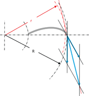
Definition of a virtual circle
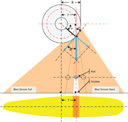
The exit point is located at the blade tip, on a circle of R radius. To measure the exit angle against the tangent at exit point, the r radius of a virtual circle to which all trajectories are tangent will be measured.
The relationship between R and r is the following one:
r = R.cos?
Where r < R and R ≠ 0 and exit angle 0 < ? < π/2
Calculation of the exit angle
Then ? can be deducted from the following equation:
? (°) = arcos(r/R)
Measurement procedure
Approximation
The method here described is based upon the approximation that the exit speed modulus and the exit angle at the blade tip are constant at any point between the head and the tail of the blast stream. This means that the ratio between relative and tangential velocity modules is considered as constant. Remember that the effect that creates the hot spot is less an exit speed modulus variation between the head and tail of blast stream than an impact angle variation, which should not be confused with the exit angle variation.
Measurement steps
1. In preparation, it is necessary to roughly set up the control cage in a way that the "hot spot" is located in front of the turbine axis, to the blast stream head. Otherwise, the impact angle at the target could never be right (90°), even if a "hot spot" can be detected, thanks to the existence of a favourable impact angle that may be less than 90°. The use of a right angle (90°) simplifies the geometric calculation and optimizes the measurement accuracy.
2. Verify that under these conditions, no bouncing happens inside the wheel-turbine housing.
3. Place a 20-25 mm diameter rod In the blast stream, parallel to the wheel-axis and approximately at 1/4th the wheel-axis to target distance,
4. Carry out a horizontal scan by moving the rod in the blast stream until the straight line crossing the shadow and the rod axis is perpendicular to the horizontal target plan, hence parallel to the vertical wheel axis.
5. Measure the distance from this line to the vertical wheel axis which is equal to r.
Scan pitch and amplitude of the rod position
• An accuracy of 0.5°; 5 mm at a rod distance from the axis turbine 575 mm is sufficient as minimum scan pitch. In order to shorten the procedure, the scan pitch for fast approach can be doubled.
• In a first approach, the rod position scan amplitude can reasonably be set between, 0.5R and R.
r = 0.5R would correspond with an exit direction of 60°.
r = R means a pure tangential exit direction with an exit angle of 0°, a null relative speed and exit speed equal to tangential speed.
Curved blade design
In this particular case, the relative velocity component is not radial but following the angle given by the blade shape and the tangent at blade tip. This does not change the method but only the result which is of course improved vs. straight blade design.
Note: thanks to this angle change, R and r are much closer to each other. This then decreases the exit angle measurement accuracy.
Influence of the mass flow rate
For a given wheel-turbine configuration, the higher the shot flow rate, the poorer the efficiency. Hence, unless the purpose is for measuring the influence of the shot flow rate upon the wheel turbine efficiency, it is recommended to use a reduced flow rate level and increase it step-by-step to find the optimal mass flow rate giving acceptable efficiency compromise.
Influence of the shot condition
For a given wheel-turbine configuration, the shot condition may influence the result. Therefore, it is recommended to operate the exit speed measurement with a "mature" shot load and not with a brand new, neither an overused shot load. Again, this could also be a topic of interest to detect what level of shot condition degradation would generate unacceptable efficiency loss.
Result example
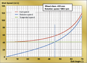
The following example chart is showing the modulus of actual exit speed and its relative and tangential components as a function of the exit angle for given wheel-turbine size and rpm.
- The tangential speed is the constant line (horizontal). Its level is depending only on the wheel size and rpm rate, not on the shot properties neither on the wheel turbine design.
- The actual exit speed starts from o°, with the modulus level of the tangential velocity, which is purely theoretical; with no relative speed, the shot acceleration and exit could not happen. Generally, wheel-turbines with poor acceleration capability are giving 15 to 20° minimum exit angle levels. At the other end of the actual curve of exit speed, no current wheel turbine design could provide an actual exit velocity higher than twice the modulus of tangential speed, which corresponds with an exit angle of 60°.
- When the exit angle is 45°, then the relative and tangential speed modulus are equal. That level of wheel performance is already very high and not even reached with the current design improvement such as curved blades or when using fine and light shot.
MFN Trainer / MONTEX Services, France
E-mail: FXAbadie@MONTEX-Services.com


