E-Archive
Science Update
in Vol. 16 - May Issue - Year 2015
Residual Stress and Component Geometry

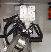
XRD residual stress measurement on a crankshaft fillet radius

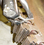
XRD residual stress measurement in the bottom of a curved turbine disk slot

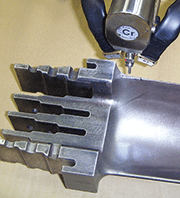
XRD residual stress measurement on the curved edge of a turbine blade
The design of functional objects is clearly one of the important characteristics determining their usefulness, and particularly their durability in service. The selection of material is another, as is the environment in which they serve. Localised surface stresses in a component can control its service life, particularly in corrosive atmospheres and in applications involving cyclic tensile loading.
This edition of Science Update considers some of the interactions between a component’s shape, manufacturing process and the compressive residual stress fields introduced to combat stress corrosion cracking and metal fatigue. Some of the challenges of measuring residual stresses in curved surfaces are also addressed.
Shapes, Materials, Machining and Stresses
Component design is largely a matter of fit and function. The finished part must perform the task for which it is intended, and be compatible with the surrounding parts, some of which may be attached to it. Surface treatments and coatings may be added to provide protection from the service environment.
Material selection is generally dictated by the gross environment expected for the part (e.g. temperature resistance, density, strength, compatibility with mating parts, etc.). More sophisticated considerations may include the material’s damage tolerance, notch sensitivity and fatigue properties.
Geometrical features of a part’s design (e.g. fillet radii, drilled holes and threads) may be necessary for the function of the part, but the stress pattern within the working part has to flow around those features. Each geometric feature can be associated with a stress concentration factor (K). Designers take stress concentration factors into account, but regions of concentrated stress have increased susceptibility to other factors, such as mechanical damage, inherent material discontinuities, and excursions from normal operating load patterns.
Machining process controls may include surface speed, depth of cut and feed. For example, in face turning surface speed is kept constant at the tool by continuously adjusting spindle speed. The depth of cut is maintained by controlling the tool path, as is the feed, which is the distance the tool advances over the face for each revolution. If the design of a disc shaped part includes a cylindrical projection from the face there will be fillet radii above and below. The machining technique to create the fillet may be to use the tool nose radius to define the fillet radius, or, if the fillet radius is to be larger, to trace around the radius in a number of spindle revolutions. In either case, as the radius is formed the machining conditions are significantly altered. Particularly, the contact zone at the cutting edge will be longer, changing the loading on the tool and its supports, and offering a different portion of the cutting edge, with a different wear history, to the part. The fillet radius with atypical machining is the same region that has an elevated stress concentration.
Tensile stress at the surface promotes stress corrosion cracking in susceptible materials, and accelerates crack initiation in metal fatigue. Conversely, the addition of a compressive residual stress at the surface provides resistance to these failure mechanisms. Compressive residual stresses can be applied to surfaces by an increasing number of processes, including shot peening, and there have been attempts to optimise machining parameters to generate inherently fatigue resistant surfaces.
It is not surprising that the designers of critical rotating components, such as those found in aircraft engines and in other applications, are making increasing use of techniques to control and minimise the risks of fatigue fracture, particularly at fillet radii, and on the walls of holes.
Creating Compressive Residual Stresses
Shot peening is undoubtedly the most widely used and successful method available to create a controlled compressive residual stress. Commercially, shot is selected from specified sizes. Shot size is one of two process parameters controlling peening intensity. Finer control is provided by adjusting the velocity of the shot at the point of impact. In wheel type machines, the rotational speed of the wheel provides this control. In air blast machines, air pressure is changed to make adjustments. The shot velocity is adjusted to find a 'saturation point' at the required intensity, where doubling the exposure time also results in a 10% increase in the arc height of the Almen strips used to plot the saturation curve. Usually, the Almen strips are placed to mimic the placement and orientation of the part to be peened.
The intensity ranges available from individual shot sizes do overlap with the ranges available from adjacent sizes. For a given intensity and coverage, larger shot will result in a smoother surface, and the risk of creating peened surface extrusion folds will be reduced. Peening areas of the part where the geometry or the manufacturing process is different may result in surfaces that do not have the same characteristics as the overall part surface. The walls of holes and fillet radii require special attention.
Specialised techniques are available to peen the walls of holes, for example using rotating lances, or by deflecting a shot stream off a conical deflector within the hole. There are modified Almen techniques to control these advanced processes. Substantial residual stresses can be introduced around holes by processes such as cold expansion, in which an oversize mandrel is forced through the hole. The addition of a protective split tube between the mandrel and the part transforms the process into sleeve cold working, which minimises the potential for smearing damage in the wall of the hole.
Fillet radii present a more complex set of problems. The radius of the fillet may be similar to the radius of the shot selected to peen the overall surface of the part. Peening a curved surface with spherical shot will result in each impact having a larger contact area than in the same process performed on a flat surface. In addition, the contact areas will not be round, but extended across the fillet radius, and diminished along the fillet. The extent of the distortion will increase and the effective intensity at the surface of the part will diminish as the shot radius approaches the fillet radius. The misshapen contact area may also result in a distorted residual stress field at each impact site. The residual stress across the fillet radius is thus often reduced more than the residual stress along the fillet. Most importantly, the maximum reduction will be in the direction most affected by stress concentration affects and altered machining conditions!
The manufacturers of critical rotating components determine a ‘safe life’ for these parts, based on repeated testing of representative components under simulated service conditions. This type of testing takes account of variations within the controlled process, and effectively finds the ‘weakest link’ in the design and manufacturing process.
Creating Localised Compressive
Residual Stresses
Other techniques are available to install residual stresses and work hardened surface layers in fillet radii, although they are not routinely used in parts such as those discussed above. Specialized bolts, for high temperature service in fatigue environments, may be manufactured with rolled (rather than machined) threads and with the head to shank fillet cold worked by rolling that fillet radius.
Some modern techniques for introducing residual stresses may be better able to treat fillet radii.
Ultrasonic peening includes several distinct processes, which use ultrasonic waves to provide energy to objects that will transfer that energy to the surface under treatment. Rather large diameter polished steel balls acting in a cloud may impact each other and a component in an enclosure. In another application of ultrasonic energy, an array of captive strikers with curved exposed faces is moved by hand or by a robot over a metal sheet, as the strikers are repeatedly driven onto the surface. The resultant ultrasonically peen-formed components may be manufactured for a unique application or as a replacement for a damaged section of a sheet metal structure, such as a wing. A similar, but perhaps less powerful, hand-held device may be used to impart beneficial residual stress to the regions around welds in similar repair operations. The ability to form the face of the striker array to conform to the shape of the surface to be peened allows an Ultrasonic Impact Treatment to be designed to deliver a controlled residual stress to specific areas of a component, including to fillet radii.
Laser Shock Peening is already widely accepted in industry, and is commercially available. Its principle of operation is to generate a shock wave at the surface of the part. A pulse of the laser beam impacts a coating on the surface of a submerged part. The pulse generates a shock wave, propagating away from the surface (rather than in the direction of the laser beam). Each pulse generates a residually stressed zone corresponding to the area impacted by the laser. The intensity of the peening effect may depend on the local angle of incidence, so with a single pass aimed into the fillet radius, the extremities may experience reduced intensity compared with the root of the fillet. When fatigue cracks occur at fillet radii, it is not unusual for their origins to be a few degrees from the run-out of the fillet radius onto an adjacent surface. Since laser shock peening is typically carried out with a series of overlapping pulses, it may be optimal to peen fillet radii with two or more overlapping beams, spanning a range from a few degrees above one of the adjacent surfaces to a few degrees above the other.
Water jet peening shares some features with Laser Shock Peening. A high-pressure water jet is formed in a nozzle equipped with an ultrasonic transducer to impart axial oscillations to the stream. The pulsating water jet breaks down into a stream of fast moving droplets. On impact with the surface, the droplets create cavitation bubbles, whose collapse generates a shock wave, cold working the surface and introducing a compressive residual stress. Prolonged and more intense exposure causes the surface to break up and erode, leading to applications for this process in the removal of otherwise durable coatings. Conventional Almen arc height measurements can be used to monitor and control intensity. The energy for peening is transferred by droplets of liquid, so the process leaves the surface shape unchanged.
Measuring Residual Stress in Curved Surfaces
The tighter the radius is, the more difficult the measurement will be!
Successful measurements require exceptional spatial resolution, with the ability to precisely locate the point of measurement in three dimensions. Most of the conventional techniques of residual stress measurement would be well beyond their resolution limits to make successful measurements of this kind. Neutron diffraction examines a volume of around 1 cubic mm. Conventional hole drilling requires a hole of about 1 mm diameter, in a surface flat enough to mount the associated strain gauges. With optical measurement of the three dimensional strains, measurements on the curved surface may be possible, but a technique to remove small but measurable volumes of stressed material without introducing new stresses would need to be defined. The Barkhausen Noise method is applicable to well-characterised magnetic materials only, and requires a substantial flat area to perform measurements. Techniques that use the velocities of near-surface ultrasonic waves also require a flat area to mount transducers, a substantial gauge length, and are susceptible to other factors, including shape, roughness and grain size that also affect the measured velocities.
Energy dispersive X-ray diffraction can be employed to perform such measurements; however, only a few facilities in the world have synchrotron beam-lines with the necessary brightness and energy range. The technique is capable of examining volumes of material small enough to provide adequate resolution, and has been used to map elastic strains around the tips of cracks in some materials. Small specimen chambers have limited this exciting technique to small samples and test coupons. If there were to be a study of machining and peening effects on residual stress distributions close to common features of machined surfaces, fillet radii should certainly be included.
X-ray diffraction methods are able to perform high-resolution residual stress measurements in small radii. However, best practices with respect to beam size versus the radius of curvature must be observed. For smaller radii, a correction to the data must be applied and measurements in two directions may be needed. A very small beam may be required to provide the required spatial resolution in the sample radius and in some applications, a rectangular beam cross section can be used to maximise the irradiated area and thus the number of coherent domains sampled. The continuity of the diffraction pattern relies on all possible orientations being present in the sampled volume and as such, large grain materials will be more difficult to characterize and may require extended sampling. A cold worked surface will help, because plastically deformed material generally provides a higher dislocation density and thus more opportunities for diffraction to occur. As the beam size is further restricted by sample geometry, it may be necessary to translate the test-piece to increase the sampled volume, requiring a particularly precise motorised specimen stage to keep the beam on a path of equivalent locations. In some instances, these details offer a challenge to every area of the instrument manufacturer’s skills, from the X-ray source to the specimen stage, and to every aspect of the operator’s skills, too.
For Information: Proto Manufacturing Ltd.
2175 Solar Crescent, Oldcastle, Ontario
Canada, N0R 1L0
Tel. +1.519.737.6330, Fax +1.519.737.1692
E-mail: proto@protoxrd.com
www.protoxrd.com


