E-Archive
Cover Page
in Vol. 17 - March Issue - Year 2016
A Brief History of Fatigue Failure Analysis, Design Theory, and Remediation

Figure 1: The United States Air Force F-22 raptor

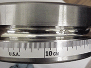
Figure 2: A pilger die

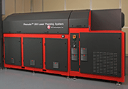
Figure 3: The Procudo
The analysis of fatigue failure using a scientific method was as an emerging field of study that originated in 1842 with the investigation of the catastrophic failure of the Versailles rail accident in Meudon, France. The axle on the locomotive broke while in transit and the carriages behind the locomotive piled into it and caught fire. More than 55 people were killed. William John Macquorn Rankine, a mechanical engineer, investigated the broken axle to understand the cause of failure. Rankine highlighted the importance of stress concentration factors in components and the impact of repeated cyclic stress on these areas that lead to the component's failure. Unfortunately, the idea he and others proposed at this time on the progressive growth of cracks due to repeated loading was ignored by other engineers. William Fairbairn shortly thereafter demonstrated the effect of fatigue on repeated flexure on large beams. Fatigue continued to remain a serious and misunderstood phenomenon for some time.
Through the 1850s and early 1910s, further work was conducted to understand the issue of repeated cyclic loading. It was during this time that the word "fatigue" was initially used by John Braithwaite to describe these common service failures. Starting in the 1910s, the origin of fatigue failure was identified as the propagation of microscopic cracks. From this observation, the relationship between cyclic stresses and the number of cycles to failure was demonstrated. Olin Hanson Basquin proposed a log-log relationship between stress (S) and the number of cycles to failure (N) based upon the test data generated by August Wöhler. Wöhler concluded that the cyclic stress range was more important than peak stress and introduced the concept of a material "endurance limit". It was not until the mid-1940s that “endurance limit” as a practical design tool began to take hold using a linear damage hypothesis to begin to predict fatigue life of a component.
The two crashes of the de Havilland Comets in 1954 caught critical attention and a need for further action. Such began the understanding of fatigue failures and approaches to reduce them through designs that mitigate the initiation and growth of cracks. The criticality of fatigue, stress risers, crack initiation and growth in metallic structures for the aerospace industry heralded a heightened level of attention in design and testing practices.
Further progress was made during the late 1950s toward understanding the fatigue process by L.F. Coffin and S.S. Manson. They demonstrated the ability to explain fatigue crack-growth in terms of plastic strain just ahead of the crack tip as the cracks propagated into the material. Plastic deformation occurs just ahead of the crack tip, leading to the propagation of the crack with each load cycle.
The real foundation for the prediction of fatigue life came in the 1960s when P.C. Paris proposed methods for predicting the rate of growth of individual fatigue cracks. He demonstrated the rate of change in the crack length versus the number of cycles. His work is popularly referred to as da/dN curves. However, M.A. Miner's popular phenomenological approach from the mid-1940s overshadowed those of Paris during this time.
Fortunately, in the last couple of decades, much progress has been made into understanding the effects of cyclic loading in materials and the mechanism involved in the propagation of cracks in metallic structures. This information, combined with Paris's methods, laid the foundation for the modern prediction of crack growth and the creation of analytical tools to predict fatigue life for various component designs. The continual increase in hazard levels associated with catastrophic failures led to new engineering design approaches and theories. Combining this knowledge with design methods increased fatigue life.
Methods of Design
This knowledge, combined with new ways of minimizing stress concentration points within a component and the continual increase in the level of the hazard associated with catastrophic failures, led to new engineering design approaches and theories involving stress and fatigue. Generally, there are two approaches used during the design of a component to determine its useful, or operational, fatigue life: Safe Life and Damage Tolerance.
Safe Life designs a component to not fail within a certain period of time or to last nearly forever during the service life of a component under a given set of operating conditions. This method requires testing and analysis to estimate the service time of a component, however, a good safety factor is added to ensure that catastrophic failure will not occur. This approach can make the component larger, heavier and less efficient than optimally desired. Helicopter blades are an examples of structures designed with this approach.
Damage Tolerance designs a component to a specific life based on using crack growth prediction methods. This approach assumes a crack or cracks already exist in the component. In this method, the fracture load where the component will fail as a result of a specific crack size is established and is known as the critical crack size. Then assuming the size of the existing cracks, the period of time for a crack to grow to this critical crack size is predicted with design tools that have been developed over the years. This approach requires da/dN curves for the material from which the component is made.
Cracks can initiate from two locations. They can start internally from a defect or flaw or they can initiate from surface defects or flaws and propagate into the component. With the understanding of these fatigue process mechanisms in metallic materials came the desire to find methods to control and mitigate the effects of fatigue crack initiation and propagation. Some of this control was obtained by understanding the effects of alloy composition, processing effects, subsequent microstructure, and material cleanliness that lent to increased fatigue lives in components. Various surface modification processes have been developed to address surface initiated fatigue, ranging from superfinishing to produce ultra-smooth surfaces to the introduction of deep surface compressive residual stresses such as from laser peening.
Surface Enhancements
The introduction of a surface modification process to enhance the fatigue capability of a metallic component has a long history, dating back to 1100 to 1400 A.D. It was used in the making of Damascus and Toledo blades. The hand/hammer peening process increased the strength and durability of the blades by adding compressive residual stresses. Various other processes to intentionally induce beneficial compressive residual stresses have been developed over time. These processes range from coining, burnishing, shot peening, to laser peening.
Shot peening initially began as a process to clean metal components (blast cleaning), later understood as a process that was also beneficial for improving fatigue. In the 1930s, John Almen (for which the Almen strip is named) found a large increase in the fatigue life of automotive valve springs with every new blast shot. Almen and Henry Fuchs developed a crude adaption of the blast clean process that eventually evolved into its current day version of shot peening. Today, technologies have been added to control the application of these various processes, meeting demands for industrial applications, and adding additional fatigue capability to components.
Laser Peening is used in a range of components, including compressor airfoils in turbine engines to automotive crankshafts to machine tools, see Figures 1 & 2. Laser Peening mitigates the effects of fatigue failures resulting from foreign object damage, stress corrosion cracking, and erosion for fatigue life extension. The depth of the compressive residual stresses induce is significantly deeper than the conventional peening processes. Fatigue lifetime increases are proportional to the depth of the compressive residual stress, which allows Laser Peening to provide service improvements significantly above those of conventional peening processes, specifically in preventing crack initiation and propagation.
In the last 20 years, additional surface enhancement technologies have been developed. Each has found use based on their individual methods and benefits in mitigating fatigue: ultrasonic peening, cavitation peening, and laser peening. Ultrasonic Peening uses an electro-mechanical method to generate compressive stresses by vibrating steel pins attached to an ultrasonic transducer. Cavitation Peening uses a jet of high-pressure water to impinge the part surface to induce stress into the part surface. Laser Peening has become a widely used and accepted industrial surface enhancement process using industrial laser peening systems as seen in Figure 3.
The Future
The continuing development of understanding fatigue failure, the evolution and development of design approaches and the discovery of methods to mitigate fatigue effects look forward to a time when they combine to produce efficient and reliable structures. While shot peening and other surface enhancements increase fatigue life and fatigue strength, they generally are not incorporated into the life prediction models of either design approach.
Modeling has certainly helped to improve the determination of component life, and these surface enhancement processes are used in a variety of applications to extend the fatigue life of components. Unfortunately at this time, the benefits of the compressive residual stresses imparted by these processes for life extension are not used in calculations for predicting the life of a component in either the Safe Life or Damage Tolerance approaches; they are primarily used as added insurance against failure adding in a safety factor.
As the level of sophistication in controlling these various surface enhancement processes increases and as the capability of the life prediction models expands to incorporate the effect of these processes, the ability to take advantage of the full benefit of these surface processes will occur. However, that is yet in the future. For now, these surface enhancement processes will be used to provide additional levels of safety and margin, keeping each of us safe from fatigue failure.
For Information:
LSP Technologies, Inc.
6145 Scherers Place
Dublin, Ohio 43016, USA
Tel. +1.614.718-3000
Fax +1.614.718-3007
E-mail: dlahrman@lspt.com
www.lsptechnologies.com


