E-Archive
Science Update
in Vol. 20 - July Issue - Year 2019
Experience With The Cosα-Method To Determine Residual Stresses In Shot Peened Spring Steel

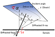
Figure 1: Scheme of the Debye-Scherrer ring

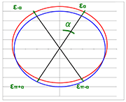
Figure 2: Displacement of the Debye-Scherrer rings under load of the sample


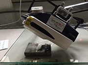
Figure 3: The used diffractometers µ-X360s (pulstec) with the leaf spring sample

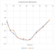
Figure 4: Residual stress distribution in dependence of the depth
1. Introduction
Today residual stress determination is often done by x-ray diffraction. The dominant method is the so-called sin2ψ-2θ-method, which is full established. To measure one value, it lasts 10 min or more depending on the spot and the number of angles you use to get a good result. In this paper, an alternative method is described, which is very powerful. It lasts less time and the spot for measuring can be changed very rapidly. The new equipment is manufactured in Japan with the name pulstec μ-X360s. It is the second generation of this equipment, which has been on the market for approximately two years.
2. Description of the cosα-method
The theoretical background of the cosα-method is not discussed here. You can read it in the following references [1, 2, 3]. A practical description is performed in this paper. The method is based on a Debye-Scherrer-measurement. X-rays were sent on the surface of the specimen, which should be measured. Because of Bragg´s Law, the incoming x-rays were reflected under a certain angle, which is dependent on the atomic spacing in the material. For details of Bragg-reflection see e. g. [4, 5]. Because of the different orientation of the atomic layers, a complete ring is reflected.
The x-ray diffractometer will radiate under a certain incident angle to the surface (in this case 35°) x-rays. The incident angel defines the direction of the measured distance of the atomic layers. A full ring is reflected as shown in Figure 1. The whole ring is detected by an area detector.
The Debye-Scherrer-ring has moved a little bit in the measuring direction, if there are residual stresses in the specimen. The situation is shown in Figure 2. For example, the red ring is the reflection without stress and the blue ring with stress.
The displacement εα1 of the ring at a certain angle α is defined as:
This displacement is proportional to cos α:
Out of the slope, the residual stress can be obtained with the help of the E-module and the Poisson ratio. All other factors are constant.
3. Experimental setup
The setup you can see in Figure 3. It shows the whole diffractometer pulstec μ-X360s without the power supply, and is about 35 cm (14 inches) long. In my case, it is used very often for the determination of shot-peened springs. Therefore, the question is, if it gives the same results as the traditional sin2Ψ-2Θ-methode (sin2Ψ-2Θ-methode, see e.g. Bob. B. He: Two-Dimensional X-Ray Diffraction [6]).
A stress-peened leaf spring sample was used and a residual stress profile into the depth was determined with the two methods. The tensile strength Rm of the sample was Rm = 1700 MPa. The material was 50 CrV 4 (1.1859). To measure the residual stresses in the depth, the material above was electrolytically removed in an area of 8 mm diameter.
In Figure 4, the measurement results are shown. The values are up to a depth of 650 µm. The differences between the two curves are measurement errors, which are for both methods around 5 %. Both residual stress distributions are compatible with each other.
5. Conclusions
Both methods give the same results for spring steel. This means the cosα-method is an excellent usable method to determine residual stresses in springs. Also, for other materials, this accordance has been achieved [7,8]. This equipment has been validated by several academic institutions and can be used in many fields.
References
[1| K. Tanaka, Y. Akiniwa: Diffraction Measurements of Residual Macrostress and Microstress Using X-Rays, Synchrotron and Neutrons, JSME International Journal Series A, 47 (2004), p. 252- 263
[2] J. Ramirez-Rico, S.-Y. Lee, J. J. Ling, I. C. Noyan: Stress measurement using area detectors: a theoretical andexperimental comparison of different methods in ferritic steel using a portable X-ray apparatus, Journal of Materials Science 51 (2016), p. 5343–5355
[3] T. Sasaki: New Generation X-Ray Stress Measurement Using Debye Ring Image Data by Two-Dimensional Detection, Materials Science Forum Vol. 783-786 (2014), p. 2103-2108
[4] H. Linder: Physik für Ingenieure, Fachbuchverlag Leipzig, München, 2014, p. 698
[5] D. C. Giancoli: Physik, Pearson, Hallbergmoos, 2018, p. 1206
[6| B. B. He: Two-Dimensional X-Ray Diffraction, John Wiley and Sons Inc., Hoboken, 2009, pp. 263
[7] D. Delbergue, D. Texier, M. Lévesque, P. Bocher:mnComparison of Two X-Ray Residual Stress Measurement Methods: Sin 2 ψ and Cos α, Through the Determination of a Martensitic Steel X-Ray Elastic Constant, Materials Research Proceedings 2 (2016) p. 55-60
[8] T. Sasaki: New Generation X-Ray Stress Measurements Using Debye Scherrer Image Data by Two-Dimensional Detection, Materials Science Forum Vols 783-786 (2014) pp 2103-2108
For Information:
Hochschule Bochum
(University of Applied Sciences)
Lennershofstr. 140
44801 Bochum, Germany
Tel. +49.234.32 10402
E-mail: eckehard.mueller@hs-bochum.de


