Introduction
Cavitation is a phenomenon of bubble formation and collapse that is harmful for hydraulic components such as pumps and valves. Cavitation bubble collapse may cause severe damage at component surfaces. However, cavitation can also be utilized for the improvement of metallic material properties in a way similar to shot peening. A peening process using cavitation impact is called “cavitation peening” [1] or “cavitation shotless peening” [2], as no shot are used in the process.
In a popular form of cavitation peening, cavitation is generated by injecting a high-speed water jet into a water-filled chamber. As shown in Fig. 1 [3], the high-speed submerged water jet called “cavitating jet” generates a cloud of bubbles [4]. Note that peening mechanism of cavitation peening is different from that of “water jet peening” in which the impact is caused by momentum transfer of the water column [1]. In a method variation used to treat outside surfaces of vessels and pipes by cavitation peening, a cavitating jet was realized in air by injecting a high-speed water jet into a low-speed water jet which is then injected in air [5].
Another method of cavitation peening involves the use of a pulsed laser. A water film is created at the sample surface, a cavitation cloud is generated by laser ablation, and the impact is produced from bubble collapse [6]. The production of bubbles from pulsed laser is termed laser cavitation. An instantaneous view of laser ablation and laser cavitation is captured by double exposure photography as shown in Fig. 2 [7].
Another way of generating cavitation bubble is the use of ultrasonic (US) cavitation that can be used as a platform for materials testing of cavitation resistance [8]. In the case of cavitation peening by ultrasound (US), the cavitation intensity changes rapidly with the distance between the US generator tip and the target surface [9]. Standard procedures for the evaluation of material resistance to cavitation erosion using a cavitating jet were standardized as ASTM G134-17 [10].
The benefits and advantages of Cavitation Peening (CP) are here overviewed briefly for the cases of cavitating jet (CP-jet), pulsed laser (CP-laser) and ultrasonic vibration (CP-US), using shot peening (SP) as reference. The fine details and quantitative results of this comparative study were presented in full in a recent review paper [1].
Fatigue strength improvement
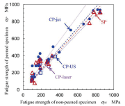
Figure 3 shows the relation between the fatigue strength of non-peened specimen σfN and the that of peened specimen σfP[1]. In [1], various metallic materials from relatively soft such as aluminum alloy to relatively hard metal such as carburized chromemolybdenum steel were reviewed. Improvement ratio kf was defined by Eq. (1),
σfP=kf σfN (1)
It was found that for 0 < σfN < 850 MPa, kf was 1.21 for CP-jet, 1.44 for CP-laser, 1.10 for CP-US and 1.15 for SP. For 0 < σfN < 400 MPa, kf was 1.47 for CP-jet, 1.44 for CP-laser, 1.10 for CP-US and 1.39 for SP.
Thus, the values of kf for CP-jet and CP-laser were slightly better than that for SP.
The effect of hardness
To reveal the material characteristics of peened surface treated by CP compared with SP, the relationship between Vickers hardness of non-peened HV_N and peened HV_P material was considered [1]. As seen in Fig. 4, HV_P was roughly proportional to HV_N . The improvement ratio kHV was defined by Eq. (2) similarly to Eq. (1),
HV_P=kHV HV_N (2)
The values of kHV were 1.40 for SP, 1.28 for CP-jet, 1.36 for CP-laser and 1.57 for CP-US. The hardening effect of SP was larger than that of either CP-jet or CP-laser. It corresponds to the results reported in [11] that the increase of dislocation density due to SP was larger than that for CP-jet and CP-laser.
Considering the hardness effect, we note that Vickers hardness is proportional to the material flow stress characteristic of the transition from elastic to plastic deformation. When hardness is measured by indentation, the presence of compressive residual stress induces additional resistive force, thus increasing the apparent hardness.
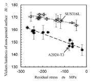
Fig. 5 (a) provides a schematic diagram of the mechanism by which the compressive residual stress is introduced into the specimen back surface. Fig. 5 (b) and (c) show the relationship between the residual stress and the apparent hardness [1]. According to Fig. 5 (a), a plate peened on the front side undergoes bending deformation so that compressive residual stress is introduced at the back surface (non-peened side). Residual stress at back surface was measured by X-ray diffraction [12], along with hardness.
As shown in Fig. 5 (b) and (c), both Vickers hardness and Rockwell superficial hardness were increased with the increase of compressive residual stress.
Figure 6 reveals the relationship between Vickers hardness of peened surface and the fatigue strength of peened specimen, in comparison with non-peened sample [1]. Fatigue strength was roughly proportional to the Vickers hardness. As shown in Fig. 6, the slope of the approximate line of non-peened and CP-jet was larger than that obtained for all data. This result suggests that a larger increase of hardness was required for SP. However, in the case of CP-jet, the larger increase of the hardness as for SP was not required. This reflects important difference in the peening mechanism, and raises a comment on the use of the hardness as key parameters to estimate the fatigue strength, as it incorporates the effect of both the yield stress and residual stress. However, when the underlying physical mechanism of peening surface improvement is different, as in the case of CP, the proportionality constant can be different.
Conclusions
To clarify the characteristics of cavitation peening (CP) compared to shot peening (SP), the data of fatigue strength and hardness of treated and non-treated surfaces were reviewed. The improvement of the fatigue strength of CP-jet and -laser was slightly better than that of SP. Hardness is a useful parameter to estimate the fatigue strength, as it includes the effect of the introduced compressive residual stress. However, the proportionality constant between the hardness and fatigue strength depends on the specific peening method and needs to be calibrated carefully to achieve design reliability.
Acknowledgement
This work was partly supported by JSPS KAKENHI Grant Number 20H02021.
Figs. 3-7 are reprinted from Journal of Materials Processing Technology, Vol. 305, H. Soyama and A. M. Korsunsky, A critical comparative review of cavitation peening and other surface peening methods, 2022, with permission from Elsevier, License Number 5344080344041.
References
[1] H. Soyama and A. M. Korsunsky, “A critical comparative review of cavitation peening and other surface peening methods,” Journal of Materials Processing Technology, vol. 305, 117586, 2022.
[2] H. Soyama, K. Saito and M. Saka, “Improvement of fatigue strength of aluminum alloy by cavitation shotless peening,” Journal of Engineering Materials and Technology, vol. 124, no. 2, pp. 135-139, 2002.
[3] H. Soyama, “Cavitation peening: a review,” Metals, vol. 10, 270, 2020.
[4] H. Soyama, “Cavitating jet: a review,” Applied Sciences, vol. 10, 7280, 2020.
[5] H. Soyama, “Introduction of compressive residual stress using a cavitating jet in air,” Journal of Engineering Materials and Technology, vol. 126, no. 1, pp. 123-128, 2004.
[6] H. Soyama, “Laser cavitation peening and its application for improving the fatigue strength of welded parts,” Metals, vol. 11, 531, 2021.
[7] H. Soyama, “Cavitation peening using pulse laser and submerged water jet to improve fatigue strength of aluminum alloy,” Journal of Material Sciences & Manufacturing Research, SRC/ JMSMR/VID/103, 2020.
[8] ASTM G32-16, “Standard test method for cavitation erosion using vibratory apparatus,” ASTM standard, vol. 03.20, 2016.
[9] F. S. Bai, K. A. Saalbach, Y. Y. Long et al., “Capability evaluation of ultrasonic cavitation peening at different standoff distances,” Ultrasonics, vol. 84, pp. 38-44, 2018.
[10] ASTM G134-17, “Standard test method for erosion of solid materials by a cavitating liquid jet,” ASTM standard, vol. 03.02, 2017.
[11] M. Kumagai, M. E. Curd, H. Soyama et al., “Depth-profiling of residual stress and microstructure for austenitic stainless-steel surface treated by cavitation, shot and laser peening,” Materials Science and Engineering A, vol. 813, 141037, 2021.
[12] H. Soyama, C. Kuji, T. Kuriyagawa et al., “Optimization of residual stress measurement conditions for a 2D method using X-ray diffraction and its application for stainless steel treated by laser cavitation peening,” Materials, vol. 14, 2772, 2021.
Hitoshi Soyama(Ph.D. in Eng.)
Professor E-mail:soyama@mm.mech.tohoku.ac.jp
Department of Finemechanics
Tohoku University
6-6-01 Aoba, Aramaki, Aoba-ku, Sendai
980-8579, Japan
Alexander M. Korsunsky
Professor,
Department of Engineering Science,
University of Oxford
Parks Road, Oxford OX1 3PJ, UK
![Fig. 1: An image of a cavitating jet injected to treat the surfaces of a gear [3]](https://www.mfn.li/storage/e-archives/article-pictures/2231/6915.gif)
![Fig. 2: A double exposure photograph of ablation and cavitation induced by a pulsed laser [7]](https://www.mfn.li/storage/e-archives/article-pictures/2231/6916.gif)

![(b) 0 < σfN < 400 MPa
Fig. 3: Improvement of fatigue strength by cavitation peening (CP) in comparison with shot peening (SP) [1]](https://www.mfn.li/storage/e-archives/article-pictures/2231/6918.gif)
![Fig. 4: The relationship of Vickers hardness of non-peened and peened surfaces [1].](https://www.mfn.li/storage/e-archives/article-pictures/2231/6919.gif)


![(c) The effect of compressive residual stress on surface hardness (Rockwell, A2024-T3).
Fig. 5: The effect of compressive residual stress on hardness [1]](https://www.mfn.li/storage/e-archives/article-pictures/2231/6922.gif)
![Fig. 6: The relationship between Vickers hardness of peened surface and fatigue strength [1]](https://www.mfn.li/storage/e-archives/article-pictures/2231/6923.gif)


