E-Archive
Science Update
in Vol. 7 - March Issue - Year 2006
Improvement of Fatigue Strength of Metallic Materials by Cavitation Shotless Peening
Author: Hitoshi Soyama (Ph. D.)
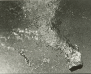
Fig. 1: Erosive vortex cavitation
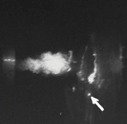
Fig. 2: Aspect of impinging cavitating jet in water
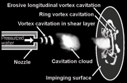
Fig. 3: Schematic diagram of cavitating jet
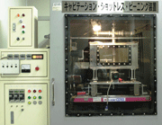
Fig. 4: Photograph of apparatus for CSP

Table 1: Shot peening condition
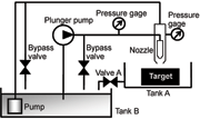
Fig. 5: Schematic diagram of apparatus for CSP
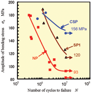
Fig. 6: S-N curve of aluminum casting alloy (JIS AC4CH-T6)
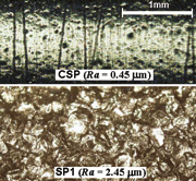
Fig. 7: Surface of peened specimen (JIS AC4CH-T6)
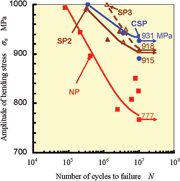
Fig. 8: S-N curve of carburized chrome-molybdenum alloy steel (JIS SCM420)
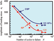
Fig. 9 S-N curve of Duralumin (JIS
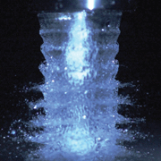
Fig. 10 Typical aspect of cavitating jet in air
Introduction
Cavitation impacts can be utilized for surface enhancement in the same way as shot peening, although cavitation impacts normally cause severe damage in hydraulic machineries such as pumps, turbines and valves. Peening using cavitation impacts is called “cavitation shotless peening (CSP)” [1]-[3], as shots are not required.
The introduction of compressive residual stress as a result of cavitation impacts has been reported by using a cavitation tunnel [4] and ultrasonic cavitation [5]. In these cases, the treatment area was limited and impact force was not large enough. Soyama et al. reported that the cavitation impacts around a submerged high speed water jet, i.e. a cavitating jet, can introduce compressive residual stress in the surface of stainless steel [6]. This was confirmed by Hirano et al. [7]. It has been revealed that there is improvement of fatigue strength [1]-[3],[8], and the effect of gettering [9],[10] by cavitation impacts produced by a cavitating jet.
In case of CSP, cavitation impact produced by a cavitating jet was used. A cavitating jet is different from normal water jets in air, even though a water jet in air can also peen a material surface. The working pressure of a cavitating jet can be higher than that of a jet in air at the same pump pressure, since the pressure at cavitation bubble collapse is utilized. The area on the material surface which is covered by the cavitating jet is much wider than that of a water jet in air. A cavitating jet is normally produced by injecting a high-speed water jet into water-filled chamber. In this paper, we call this a cavitating jet in water. Recently, Soyama successfully generated suitable cavitating jet in air for CSP by injecting a high-speed water jet into a concentric low-speed water jet, which is injected directly into air without water-filled chamber [11],[12]. The ability of optimized cavitating jet in air is greater than that of a cavitating jet in water [11]. A cavitating jet in air has been tried to peen forming [13]. Peening using a water jet based on the authors’ research is now applied for suppression of stress corrosion cracking in nuclear power plants [14].
In the present paper, in order to make clear the mechanism of this novel peening method without shots by CSP, the cavitating jet is explained. The improvement of fatigue strength of metallic materials by CSP is then revealed and compared with that of shot peeing.
Cavitation and Cavitating Jet
Cavitation bubbles occur in liquid at low-pressure produced by an increase of flow velocity. Shock waves and micro jets are produced at bubble collapse, and these cause impact force. A lot of research has been carried out into single spherical cavitation bubbles experimentally and numerically. Soyama et al. found that the vortex cavitation consists of tiny bubbles produced by severe erosion in the pump [15]. This means that the erosive vortex cavitation produced large impacts. This fact was confirmed by numerical simulation [16]. Figure 1 shows typical erosive vortex cavitation downstream of the butterfly valve, which was observed by using a clear acryl pipe [17]. White bubbles are cavitation bubbles and the tiny bubbles form vortex cavitation. It is noted that the powerful cavitation is vortex cavitation and not spherical bubble cavitation. At the view point to get powerful impact, it is necessary to produce such erosive vortex cavitation at high-efficiency.
Impinging of a cavitating jet produces erosive vortex cavitation at high-frequency. Figure 2 reveals aspect of an impinging cavitating jet in water. A special sensor, which can detect the impact force, was set on the impinging surface, as indicated by the white arrow. As output signal from the sensor and flush lamp, whose exposure time was in 1.1 µs, was synchronized, Fig. 2 shows the cavitating jet when the impact was produced. Figure 3 illustrates a schematic diagram of the cavitating jet using high-speed photographs such as Fig. 2. The small vortex cavitation initiates in the low pressure region of the vortex core, which takes place in shear layer around a high-speed water jet, and the vortex cavitation combined together then forms a big cavitation cloud. The cloud shedding was a periodical phenomena, whose frequency was several kHz. The cloud was impinged to the surface and became a ring vortex cavitation. At the collapse, a part of the ring formed an erosive vortex cavitation. The cavitating jet is very useful for practical use of cavitation, as the cavitating jet can produce cavitation where cavitation impact is required and it produces powerful vortex cavitation at high frequency.
The key parameter for a cavitating jet is the cavitation number T. The cavitation number is defined by the injection pressure of the high-speed water jet p1, pressure of tank p2, where specimen was set, and the saturated vapor pressure of the test water p? as follows:
Due to formatting problem, the formula can not be shown on-line. Ask for a PDF copy. (1)
The pressure in Eq. (1) was absolute pressure. In the case of a cavitating jet, the cavitation number can be simplified as in Eq. (1) because p1 >> p2 >> p?. For the case of cavitating jet in air, p2 is the low-speed water jet. At certain cavitation number ? ? 0.01 for cavitating jet in air and 0.014 for cavitating jet in water, cavitation intensity had a maximum at constant injection pressure p1.
Figure 4 shows one apparatus for CSP developed by the author. The cavitating jet in air and water can be used for CSP by using the apparatus. The test specimen for a fatigue test and machinery parts such as gear can be treated. Figure 5 illustrates a schematic diagram of the apparatus. The test nozzle consists of a nozzle for the high-speed water jet and a nozzle for the low-speed water jet. The nozzles were set in a concentric configuration. The diameter of the nozzle for the high-and low-speed water jets were 1 mm and 20 mm, respectively. The injection pressure of the high-speed water jet and low-speed water jet were controlled by opening bypass valves. The high-speed water jet was pressurized by a plunger pump and the low-speed water jet was pressurized by a submerged turbine pump, respectively. For testing the cavitating jet in air, valve A on tank A was opened. To examine the cavitating jet in water, valve A was closed to allow tank A to fill.
Improvement of Fatigue Strength
Figure 6 illustrates results of a rotating bending fatigue test for not-peened specimen (NP) and specimen treated by cavitation shotless peening (CSP) and shot peening (SP). Tested material was heat-treated aluminum casting alloy with heat treatment (Japan Industrial Standard JIS AC4CH-T6). In case of CSP, the cavitating jet in water was used. Cavitation shotless peening conditions were as follows: nozzle diameter of water jet d = 1.8 mm, injection pressure p1 = 30 MPa, pressure of water filled tank p2 = 0.42 MPa, cavitation number ? = 0.014, standoff distance s = 55 mm scanning speed ? = 30 mm/min. Shot peening condition SP1 was shown in Table 1. In the case of shot peening, the condition SP1 is the best condition for JIS AC4CH-T6 [19]. Regarding Little’s method [18], the fatigue strength at 107 was 93 MPa for not-peened NP, 120 MPa for SP1 and 156 MPa for CSP. Namely, CSP can improve the fatigue strength and it is better than the shot peening. As the residual stress of NP was about -60 MPa and that of CSP was -160 MPa, the introduction compressive residual stress was main reason of improvement of fatigue strength. Figure 7 illustrates the aspect of the surface of specimen. Although the shot peened surface was very rough, the polishing line on the surface was revealed on the surface of CSP. The increase in roughness of CSP is much smoother than that of SP1. The main reason is that the fatigue strength of CSP is larger than that of SP1.
Figure 8 illustrates the S-N curve of carburized chrome-molybdenum alloy steel (JIS SCM420) investigated by a rotating bending fatigue test. The cavitating condition was the same as mentioned above. The scanning speed was 3 mm/min. Shot peening conditions SP2 and SP3 were shown in Table 1. The fatigue strength at 107 was 777 MPa for NP, 915 MPa for SP1, 918 MPa for SP2 and 931 MPa for CSP. Namely, CSP can enhance the fatigue strength of not only soft materials such as aluminum alloys, but also hard materials such as carburized steel. Actually, the residual stress of CSP specimen had maximum compression -553 MPa at depth z = 0 µm, i.e. on the specimens surface. The specimen of SP2 had a maximum residual stress of -1,106 MPa at 91 µm and that of SP3 was -1,327 MPa at 34 µm. The improvement of fatigue strength by CSP is slightly better than that of SP2 and SP3, even though the compressive residual stress of CSP was not so large. The maximum compressive value and its depth are not main parameters when the peening method was different, as CSP and SP differ in kind from each other.
Figure 9 illustrates S-N curve of Duralumin (JIS A2017) for not-peened and peened specimen by CSP using the cavitating jet in air. CSP condition was follows: nozzle diameter of water jet d = 1 mm, injection pressure of high-speed water jet p1 = 20 MPa, injection pressure of low-speed water jet p2 = 0.21 MPa, cavitation number ? ? 0.01, standoff distance s = 45 mm, scanning speed ? = 3 mm/min. The fatigue strength using Little’s method at 107 cycles for the not-peened specimen was 120 MPa while that of CSP was 185 MPa. CSP by using a cavitating jet in air improves fatigue strength of duralumin more than 50 %.
Figure 10 illustrates the typical aspect of the cavitating jet in air at optimum condition [12]. The high speed water jet was injected into the low-speed water jet, which was injecting into air. The cavitation bubble as can be seen was white cloud in the low-speed water jet. The cloud was shedding periodically. The low-speed water jet revealed the wavy pattern. The frequency of wavy pattern and cloud shedding were synchronized at the optimum condition, where the jet capability had a maximum.
Conclusions
The cavitation shotless peening (CSP) has been introduced including how to produce powerful cavitation. The results of improvement of fatigue strength by CSP were revealed and compared with shot peening. CSP can enhance the fatigue strength the same way as shot peening. The great advantage of CSP is that the peened surface is much smoother than shot peened surface, as CSP can peen the surface without solid collision.
This work was partly supported by the Japan Society for the Promotion of Science under the Grant-in-aid for Scientific Research (B)(2) 17360047 and the Ministry of Economy, Trade and Industry 13HC2016.
References
1. Soyama, H., Saito, K. and Saka, M., 2002, “Improvement of Fatigue Strength of Aluminum Alloy by Cavitation Shotless Peening,” Journal of Engineering Materials and Technology, Trans. ASME, Vol. 124, No. 2, pp. 135 – 139.
2. Odhiambo, D. and Soyama, H., 2003, “Cavitation Shotless Peening for Improvement of Fatigue Strength of Carbonized Steel,” International Journal of Fatigue, Vol. 25, Nos. 9 – 11, pp. 1217 – 1222.
3. Soyama, H. and Macodiyo, D.O., 2005, “Fatigue Strength Improvement of Gears Using Cavitation Shotless Peening,” Tribology Letters, Vol. 18, No. 2, pp. 181 – 184.
4. Blickwedel, H., Haferkamp, H., Louis, H. and Tai, P.T., 1987, “Modification of Material Structure by Cavitation and Liquid Impact and their Influence on Mechanical Properties,” Proceedings of 7th International Conference on Erosion by Liquid and Solid Impact, Cambridge, pp. 31-1~31-6.
5. Rawers, J.C., McCune, R.A. and Dunning, J.S., 1991, “Ultrasound Treatment of Centrifugally Atomized 316 Stainless Steel Powders,” Metallurgical Transactions A, Vol. 22A, pp. 3025 – 3033.
6. Soyama, H., Yamauchi, Y., Ikohagi, T., Oba, R., Sato, K., Shindo, T. and Oshima, R., 1996, “Marked Peening Effects by Highspeed Submerged-Water-Jets - Residual Stress Change on SUS304 - ,” Journal of Jet Flow Engineering, Vol. 13, pp. 25 – 32.
7. Hirano, K., Enomoto, K., Hayashi, E. and Kurosawa, K., 1996, “Effects of Water Jet Peening on Corrosion Resistance and Fatigue Strength of Type 304 Stainless Steel,” Journal of the Society of Materials Science, Japan, Vol. 45, pp. 740 – 745.
8. Soyama, H., Kusaka, T. and Saka, M., 2001, “Peening by the Use of Cavitation Impacts for the Improvement of Fatigue Strength,” Journal of Materials Science Letters, Vol. 20, No. 13, pp. 1263 – 1265.
9. Soyama, H. and Kumano, H., 2000, “Oxidation-Induced Stacking Faults Introduced by Using a Cavitating Jet for Gettering in Silicon,”, Electrochemical Solid-State Letters, Vol. 3, No. 2, pp. 93 – 94.
10. Kumano, H., Sasaki, T. and Soyama, H., 2004, “Evaluation of the Effectiveness of Backside Damage Gettering in Silicon Introduced by a Cavitating Jet,” Applied Physics Letters, Vol. 85, No. 16, pp. 3935 – 3937.
11. Soyama, H., 2004, “Introduction of Compressive Residual Stress Using a Cavitating Jet in Air,” Journal of Engineering Materials and Technology, Trans. ASME, Vol. 126, No. 1, pp. 123 – 128.
12. Soyama, H., 2005, “High-Speed Observation of a Cavitating Jet in Air,” Journal of Fluids Engineering, Trans. ASME, Vol. 127, No. 4, pp. 1095 – 1101.
13. Soyama, H. and Saito, K., 2003, “Peen Forming by Using a Cavitating Jet in Air,” Proceedings of the 7th Pacific Rim International Conference on Water Jetting Technology, pp. 429 – 436.
14. Soyama, H., 2004, “Fracture, Its Evaluation and Suppression: III Surface Modification for Suppression of Crack Initiation and Propagation,” Journal of the Society of Materials Science, Japan, Vol. 53, pp. 826 – 832.
15. Soyama, H., Kato, H. and Oba, R., 1992, “Cavitation Observations of Severely Erosive Vortex Cavitation Arising in a Centrifugal Pump”, Proceedings of 3rd International Conference on Cavitation, Cambridge, pp. 103 – 110.
16. Wang, Y.C. and Brennen, C.E., 1998, “Observations of Shock-Waves in Cloud Cavitation,” Journal of Fluid Mechanics, Vol. 355, pp. 255 – 283.
17. Soyama, H., Ohba, K., Takeda, S. and Ohba, R., 1994, “High-Speed Observation of Highly Erosive Vortex Cavitation around Butterfly Valve,” Trans. JSME, Ser. A., Vol. 60, No. 572, pp. 1133 – 1138.
18. Little, R.E., 1972, “Estimating the Median Fatigue Limit for Very Small Up-and-Down Quantal Response Tests and for S-N Data with Runouts,” Probabilistic Aspects of Fatigue, ASTM STP 511, pp. 29 – 42.
19. Masaki, K., Matsumura, T. and Ochi, Y., 2001, “The Improvement of High Cycle Fatigue Properties of AC4CH Alloy with Shot Peening,” Proceedings of the 2001 Annual Meeting of JSME/MMD, pp. 259 – 260.
E-mail: soyama@mm.mech.tohoku.ac.jp
Department of Nanomechanics,
Tohoku University
6-6-01 Aoba, Aramaki, Aoba-ku
Sendai, 980-8579, Japan


