E-Archive
Science Update
in Vol. 11 - March Issue - Year 2010
Laser Peening For Improving Metallic Components

Fig 1: Photographic presentation of Laser Peening experimental setup
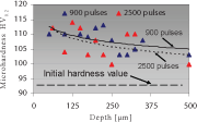
Fig 2: Microhardness variations in the surface
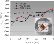
Fig 3: Variation of minimal principal residual stresses
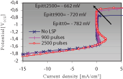
Fig 4: Comparison of potentiodynamic curves in the presence of 35g/L NaCl
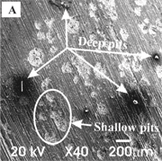
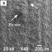
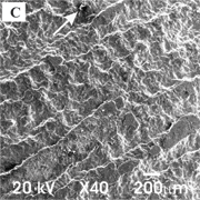
Fig 5: SEM macrographs of pit sites at the specimen surface of aluminium alloys. A
Introduction
Suitable variation of residual stress profiles, fatigue strength and frequently also corrosion resistance of a material, are key requirements to be fulfilled for usability and long life of a vital machine component.
Laser Peening (LP) is an innovative surface treatment which was initially developed for the aeronautic industry as the method for the improvement of the fatigue cracking resistance of the turbine spades of an aircraft, such as Falcon F-16 and Rockwell F-22. LP is based on plasma generation, which produces shock impact waves, which, in turn, produce elastoplastic shifts of atomic planes and generation of compressive residual stresses of high gradient [1]. LP has been applied to different types of steels, aluminium and titanium alloys [2]. In practice, technologists and engineers frequently require the introduction of compressive residual stresses since it improves fatigue resistance of a material [3, 4]. In the study [5] of the effects of LP parameters such as laser-beam power density, pulse duration, and pulse density it was found that a correct choice of the processing parameters enabled desired variations of micro-hardness and residual stresses in the surface of machine components. Such achieved condition provided improved material resistance to fatigue. The applicability of laser peening was also confirmed to improve stress-corrosion cracking [6].
Experimental Procedure
For a comparison of the effect of shock waves aluminium alloy, i.e. AlSi1MgMn in the precipitation-hardened state T-651, was chosen. The chemical composition of the aluminium alloy was: 0.98 % Si, 0.67 % Mg, 0.53 % Mg, 0.25 % Fe, 0.03 % Ti, 0.01 % Cr, 0.01 % Zn and the remainder Al. Specimens were cut from a round drawn rod of Ø40 mm to uniform discs of 8 mm in height with an average value of the surface areal roughness Sa=0.55 ?m.
Laser peening was performed with a Q-switched Nd:YAG laser operating at 10 Hz with a wavelength of 1064 nm. System delivered energy of 1.9 J, spot diameter was 1.5 mm and therefore power density was equal to 10.75 GW/cm2.
Figure 1 shows the experimental setup used for surface treating with laser shock waves, the specimen being fixed to a moving table and immersed into water. Two pulse densities were used, i.e. 900 and 2500 pulses/cm2 and the laser treated region on each specimen was 20 x 20 mm.
Microhardness Profiles After Laser Peening
Microhardness through depth variations were made by 200 g load and 20 s load time.
Figure 2 shows through-depth microhardness variations in the hardened layer using different pulse density level. The microhardness results confirm that with given hardening conditions a stronger effect of shock waves at the surface can be achieved with a higher pulse density per area unit. The highest microhardness value of 114 HV0.2 was measured at the specimen after treatment 2500 pulses/cm2. After treatment with 900 pulses/cm2 microhardness of 112 HV0.2 was achieved. In comparison to the untreated material, with microhardness of 92 HV0.2, the microhardness at 900 pulses/cm2 increased by 21.7 % whereas at the specimen treated with 2500 pulses/cm2 23.9 % increase was observed.
From Fig. 2 it is also obvious that the trend-line, calculated by the linear regression, indicate higher through depth microhardness value at the specimen which was treated with lower pulse density level. The major dissipation of the measured microhardness values is attributed to the size of an indentation calotte and small loads used for measurement since the alloys contain both the softer phase ? and the harder ? intermetallic phase.
Residual Stresses After Laser Peening
Residual stress profiles in the thin surface layer were determined by the relaxation hole-drilling method in accordance with ASTM E837 standard [7], along with RS-200 Milling Guide, Vishay Group.
Distribution of minimal residual stress profiles as a function of depth are shown in Fig. 3. It can be inferred that the values of the residual stresses in the specimen in the initial state are ideal and they amount to around 0 MPa, which confirms an adequate heat treatment condition T-651.
The analysis of the principal residual stresses after laser peening of the specimens with a power density of 10.75 GW/cm2 confirmed that the influence of pulse density is important. With the pulse density of 900 pulses/cm2 compressive residual stresses of -242 MPa are obtained in a depth of 0.033 mm whereas with the higher pulse density, i.e. 2500 pulses/cm2, they are even higher, i.e. -317 MPa.
Corrosion Tests After Laser Peening
Investigation of pitting corrosion was performed by the potentiodynamic polarisation tests, conducted with Voltalab 21 potentiostat/galvanostat, Radiometer Analytical. The specimens were exposed to the 3.5% NaCl water solution in the CEC/TH corrosion cell at a a scan rate of 10 mV/s. A Pt electrode was used as a counter electrode, whereas the XR110 Calomel electrode with saturated KCl was used as a reference electrode.
Potentiodynamic polarisation curves of the specimens measured prior to and after the laser peening are shown in Fig. 4. After 60 min stabilization at the open-circuit potential, following the active region, the aluminium alloy specimens exhibits passive behaviour. Corrrosion tests showed an increase in the pitting potential of the laser peened specimens. Specimen treated with 900 pulses/cm2 had an increase in the pitting potential of + 62 mVSCE, where with 2500 pulses/cm2 an increase of +120 mVSCE was established, compared to the specimen without laser treatment.
For an additional confirmation of improved corrosion resistance after LP, the specimens were verified also with the SEM microscope (Fig. 5). In accordance with an ASTM standard [8], the specimen surfaces were subjected to a preliminary cleaning action.
From image analysis it can be noted that there is a high level of shallow pitting and also deeper pitting attack at the specimen surface without laser treatment, whereas on the treated specimen surface it is in much better condition. That confirms that with a higher pulse density the number of pits will reduce.
Conclusions
Laser Peening turned out to be a very efficient technique to improve surface integrity and corrosion resistance. On the basis of the micro plastic deformation induced by shock waves, an increased dislocation density in the specimen surface was obtained. The gradient of dislocation piling through the specimen depth improved microhardness and residual stress profiles and resistance to pitting corrosion of the material.
An increase of microhardness at the surface was noticed under all processing conditions. As expected, it increased with a larger number of processing iterations as a consequence of higher degree of laser spot overlapping.
The compressive principal residual stress profiles in the thin surface layer confirmed an exceptionally favourable variation after laser treatment. The favourable residual stress profiles indicate higher material resistance to damage under dynamic loading of machine components.
Corrosion testing confirmed a pitting corrosion attack, both in the as-delivered state and in the treated state. The intensity of pitting corrosion attack, however, decreases with the increase in pulse density, also an increase in pitting potential with the higher pulse density was confirmed.
References
1. Grum, J., Trdan, U., Hill, M.R. (2008) Materials Sci. For. Vol. 589, pp 379-384.
2. Zhang, W., Yao, Y.L. (2002) Journal of Manufacuring Science and Engineering , Vol. 124, p.p. 369-378.
3. Hammersley, G., Hackel, L. A., Harris, F. (2000) Optics and Lasers in Engineering Vol. 34, p.p. 327-337.
4. Ocaña, J.L., Molpeceres, C., Porro, J.A., Gómez, G., Morales, M. (2004) Appl. Surf. Sci. 238, p.p. 501-505.
5. Hong, Z., Chengye, Y. (1998) Materials Science and Engineering A257, p.p. 322-327.
6. Y. Sano, et. al. Proceedings of ICONE 15: 15th International Conference on Nuclear Engineering, Agoya, Japan, 2007.
7. ASTM Standard ‘Standard Test Method for Determing Residual Stress by the Hole Drilling Relaxation method’, ASTM E 837-01, ASTM Int., USA.
8. ASTM Standard (2003) ‘Standard Practice for Preparingm Cleaning, and Evaluating Corrosion Test Specimens (G1-03)’, ASTM Int., West Conshohocken, USA.
Prof. Dr. Janez Grum(a)*
E-mail: janez.grum@fs.uni-lj.si
Asist. Uroš Trdan(a)
E-mail: uros.trdan@fs.uni-lj.si
Prof. Dr. José Luis Ocana(b)
E-mail: jlocana@etsii.upm.es
Mr. Juan A. Porro(b)
E-mail: japorro@etsii.upm.es
(a) University of Ljubljana, Faculty of Mechanical Engineering, Ašker?eva 6, 1000 Ljubljana, Slovenia, *Corresponding Author
(b) Centro Láser U.P.M., Carretera de Valencia km. 7,300, 28031 Madrid, Spain


