E-Archive
Science Update
in Vol. 21 - January Issue - Year 2020
Laser Shock Peening For Fatigue Life Extension In Aerospace Structures

Figure 1: In-plane strain map from a laser-shock peened sample, showing compressive residual strain directly below the peened surface. The white dashed lines, labelled A, B, and C, show the positions of line profiles of strain that are plotted in: (b) line profiles from lines A, B and C, showing the strain profile at various depths. The effective width of the peened area can be observed. Full information can be found in our paper3

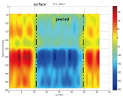
Figure 2: Depth profile of residual strains across a peened patch in aluminium alloy AA2024, measured at the BESSY synchrotron in Berlin. The peening was performed on the top surface as shown on the figure, at 0 µm depth (no data are available in the first 50 µm using this technique. Note that, because of the lower strength of the clad layer (typically around 100 MPa yield strength), the near-surface strains are lower than those below 250 µm depth

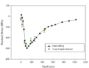
Figure 3: Determination of a near-surface residual stress profile from laser peening using two experimental techniques, one based on strain relief and one based on lattice diffraction
Introduction
Laser shock peening (LSP) has developed rapidly as a manufacturing process, from the initial scientific observations of laser/surface interactions in the 1960s, to its deployment in the aerospace and nuclear power industries.
The first scientific publication of what we would now recognise as laser peening was in the 1970s1, with an associated patent2.
High-value engineering integrity problems drove the industrial application of laser peening. In the US, foreign-object damage (FOD) mitigation on the fan blades of the B-1B engine showed that LSP had the potential not only to recover the fatigue life of a damaged blade, but to enhance the life even after the damage had occurred. In Japan, the problem of stress corrosion of welds in the pressure vessels of operating nuclear power plants led to a different technological solution for LSP: with a system that could be operated remotely inside a reactor vessel during a maintenance shutdown, and that did not use a sacrificial layer because of the impracticality of accessing the area to be peened.
LSP has become a standard treatment for fan blades in aero-engines, particularly for treating the blade root sections where they are inserted into the discs and are then subjected to fretting fatigue. It has also been applied in high-profile repair applications, such as the titanium wing lugs for the F-22 fighter that required remediation in order that the fatigue design life goal would be met.
Developments in laser peening
Over the last ten years, there has been increasing interest in the deployment of laser peening into a wider range of applications, including marine structures, nuclear waste vessels, and civil aerospace structural applications. This has lead to technical challenges in the application of the peen technique to different geometries and in different manufacturing environments, and scientific challenges in the derivation of the "best" peening parameters to use for a particular material in a particular geometry.
The technical challenges include the difficulty of applying LSP in a flexible, modular way in a modern manufacturing environment, that might perhaps require access in restricted spaces in a partly-assembled airframe, for example. Currently, the laser systems that are used are far from portable, and using optical fibres to deliver the lasers is not possible because of breakdown of the fibre materials at the power densities used. In some manufacturing environments, the water confinement layer used in the process is a problem because of the difficulty of containing and removing the water following the processing.
Technically, therefore, much of the effort in the laser side of LSP research has been towards more compact laser systems, easier beam delivery, and alternatives to using water as a confinement layer. On the application side, research has been focussed on the optimum way of applying LSP to specific problems, peening materials that have not been peened previously, and in geometric sections that pose challenges: because, for example, they feature thin sections with limited elastic constraint; require peening near edges or discontinuities where it is difficult to predict the outcomes with certainty; or for novel materials including ceramics and polymers, and metallic systems that have limited ductility.
Research at Coventry
At Coventry University, research in recent years has been directed towards improving understanding of laser shock peening and its effects in aerospace applications. The work has encompassed determination of residual stress following laser shock peening, and the effect of laser shock peening on fatigue life improvement of aerospace aluminium alloys, specifically in section thicknesses relevant to use in fuselage and wing skin components.
Comprehensive experimentation has been performed for the analysis of residual stress. At Coventry, we use X-ray diffraction, incremental hole drilling using equipment from Stresscraft Ltd in the UK, and the contour method.
We also access the international neutron and synchrotron X-ray facilities that offer significant advantages over laboratory-based techniques in the non-destructive determination of residual strains deep (up to several millimetres depth) within engineering components. As an example, Figure 1 shows measurements made using neutron transmission strain imaging of the strain field produced from laser peening of a thin (2-mm-thick) aluminium plate.
Figure 2 shows a map produced by high-energy synchrotron X-ray radiation of the residual strain profile in cross-section across a peened region in aerospace aluminium. In this case, the aluminium plate had a clad layer of pure aluminium on the surface: this layer, of ~100 µm thickness, is roll-bonded to the higher-strength alloy in order to provide corrosion resistance.
Validation of residual stress analyses using different experimental techniques is very important in supporting development programmes where the results are used to inform the selection of process parameters, and in assuring that an appropriate magnitude and profile of residual stress has been generated that will then provide the required degree of improvement in life. Figure 3 gives an example of a cross-validation of the peen stresses near a surface, using both incremental hole drilling, and X-ray diffraction coupled with layer removal to obtain a depth profile. The results are in excellent agreement, giving high confidence in the accuracy of the data.
In summary, there is still much research to be done on the application of laser peening to new materials systems, and in the development of the technology to allow more flexible application in manufacturing industry. Residual stress will remain as one of the key criteria for which laser peening is applied. There is a range of techniques, both destructive and non-destructive, available for the determination of residual stress; some of which can be applied in the laboratory and some of which require the use of specialist large-scale facilities. None of them is ideal for all materials and all geometries, so validation using multiple methods is often required for assurance of the data, particularly when development of treatments for safety-critical components is under development.
Acknowledgements
The research team at Coventry University who have contributed to this work, led by Professor Fitzpatrick, includes Dr Niall Smyth, Dr Marco Pavan, Dr Stefano Coratella, and Mr Mitchell Leering. Funding for the research has been provided by the US Air Force Research Laboratory, through the European Office of Research and Development; and from Airbus UK and Airbus GmbH. Professor Fitzpatrick wishes to thank Dr Domenico Furfari, Dr Kristina Langer, Professor José Ocaña, Professor Claudia Polese, and Dr Burak Toparli for their support of this research.
For Information:
Coventry University, Priory St
Coventry CV1 5FB, UK
E-mail: michael.fitzpatrick@coventry.ac.uk


