Introduction
Additively manufactured metallic materials, i.e., 3D-Metal, are useful metals for medical implants and aviation components, as the shapes are formed directly from CAD/CAM data. It is possible to achieve topologically optimal shapes that are difficult to produce using conventional machining methods such as milling. However, the low fatigue strength of as-built 3D-Metal is an obstacle to its practical applications. Thus, a mechanical surface treatment that can improve the fatigue strength of as-built 3D-Metal to a level comparable to that of hot-rolled metals is required.
It has been reported that surface smoothing and the introduction of compressive residual stress are effective in improving the fatigue strength of as-built 3D-Metal [1–6]. In cavitation abrasive surface finishing (CASF), the impacts caused by the collision of abrasives in a submerged water jet are smoothed out, and the cavitation collapse impacts introduce compressive residual stress. However, the optimum jet pressure for accelerating the abrasives differs from the optimum jet pressure for generating aggressive cavitation impacts. In submerged laser peening (SLP), although laser ablation (LA) smooths the surface and the bubble collapse impact of laser cavitation following LA introduces compressive residual stresses, thereby improving fatigue strength, the process has the disadvantage of being excessively time-consuming [2]. Note that conventional shot peening (SP) is unable to treat the valleys in as-built 3D-Metal, resulting in poor fatigue strength improvement [2]. It is generally said that the fatigue strength of 3D-Metal is about half that of hot-rolled material; however, as the fatigue properties of Ti6Al4V vary significantly depending on heat treatment, it is necessary to compare their fatigue properties when subjected to the same heat treatment.
In the present column, a combined process of fine particle bombarding (FPB) for surface smoothing and cavitation peening (CP) for the introduction of compressive residual stress is used to improve the fatigue strength of as-built powder bed fusion laser sintering titanium alloy PBF-LS/Ti6Al4V, comparing it with hot-rolled Ti6Al4V and other mechanical surface treatments.
Material and Methods
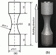
Figure 1 shows the fatigue specimen of PBF-LS/Ti6Al4V. The diameter of the test section was 5.0 mm for as-built PBF-LS/Ti6Al4V and 4.6 mm for hot-rolled Ti6Al4V, as the surface of as-built PBF-LS/Ti6Al4V was removed by FPB. Both hot-rolled Ti6Al4V and PBF-LS/Ti6Al4V were treated by the same solution annealing and aging procedure [5].
The as-built PBF-LS/Ti6Al4V was treated by FPB, CP, SLP, SP, and their combined process. At present, in SP, shot was accelerated by a water jet; then it was denoted as SPwj.
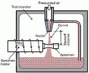
Figure 2 illustrates the schematic of FPB. The density and equivalent diameter of the used garnet were 3.947 ± 0.008 g/cm³ and 130 ± 29 μm, respectively. The garnet was injected through the 2.6 mm diameter nozzle by an air pressure of 0.7 MPa. In FPB, the garnet was recirculated in the chamber. The standoff distance from the nozzle to the specimen surface was 11 mm. The specimen was moved in the axial direction with rotation at a 2 mm pitch by the specimen holder. The processing time per unit length, tp, was defined by the number of scans, n, and the scanning speed, va, in the axial direction as follows.
tp = n/va (1)
Figure 3 shows the test section of the CP system. In CP, the water jet, whose injection pressure was 30 MPa, was injected perpendicularly onto the specimen, which was placed in the water-filled chamber through the 2 mm diameter nozzle. The pressure in the chamber was controlled by a downstream valve. The standoff distance from the upstream corner of the nozzle to the specimen surface was 80 mm. The pressure in the chamber was set to 0.42 MPa (absolute pressure) to enhance the cavitation aggressivity. The specimen was moved in the axial direction with rotation, similar to FPB.
The fatigue life was evaluated by a moment-controlled torsional fatigue tester, and the fatigue strength was measured by a displacement-controlled torsional fatigue tester. The fatigue strength at 107 was calculated by Litte’s method [7].
The residual stress, σR, was evaluated by the sin²ψ method using an X-ray diffraction apparatus. To consider ψ-split, 12 diffraction patterns were detected at ψ = 0°, 20.27°, 29.33°, 36.87°, 43.85°, and 50.77°, changing with Φ = 0° and 180°. The exposure time per frame at each position was 5 min. The surface roughness, the arithmetic mean roughness, Ra, was measured by a confocal laser microscope.
Experimental Results
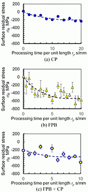
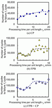
Figures 4 and 5 show the surface residual stress, σR, and the number of cycles to failure, Nf, at τa = 460 MPa, changing with the processing time per unit length, tp, respectively. The compressive σR values of CP, FPB, and FPB + CP increased with tp and then saturated. The Nf of CP increased with tp. On the other hand, the Nf of FPB and FPB + CP slightly decreased at tp = 2–3 s/mm and then increased. In this range, surface defects appeared, and they became crack initiation points. Considering the results of Fig. 5, the optimum processing time was defined as 16 s/mm for CP, 6 s/mm for FPB, and 6 s/mm for CP after FPB.
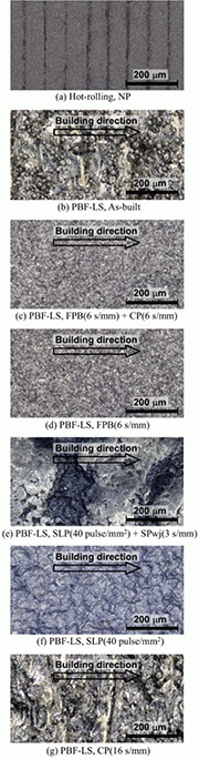
Figure 6 shows the appearance of (a) hot-rolled Ti6Al4V, (b) PBF-LS, as-built, (c) PBF-LS, FPB + CP, (d) PBF-LS, FPB, (e) PBF-LS, SLP + SPwj, (f) PBF-LS, SLP, and (g) PBF-LS, CP, observed by a digital microscope. On the hot-rolled surface, tool marks made by a lathe were observed. On the as-built PBF-LS surface, there were particles and deep valleys. FPB can remove these surface defects.
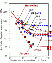
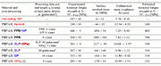
Figure 7 illustrates the S-N curves for hot-rolled Ti6Al4V and treated PBF-LS/Ti6Al4V, together with the as-built material. Table 1 shows the fatigue strength at Nf = 107, i.e., τf exp, the surface residual stress, σR, and the arithmetic mean roughness, Ra. The τf exp was 210 ± 10 MPa for as-built PBF-LS/Ti6Al4V and 347 ± 26 MPa for hot-rolled Ti6Al4V. Namely, τf exp of as-built PBF-LS/Ti6Al4V was 60% of that of hot-rolled Ti6Al4V. After FPB + CP, τf exp was 446 ± 5 MPa. It was 1.28 times larger than τf exp of hot-rolled Ti6Al4V. This means that we have succeeded in improving τf exp of as-built PBF-LS/Ti6Al4V to a level that exceeds τf exp of hot-rolled Ti6Al4V by FPB + CP. The main reason for this is that FPB reduced Ra from 12.54 μm to 7.25 μm. Furthermore, CP introduced a compressive residual stress of 446 MPa. As shown in Table 1 and Fig. 7, although τf exp of SPwj [2] was 285 ± 10 MPa, it became 381 ± 10 MPa after treatment by SLP + SPwj. In the case of SPwj, the bottoms of the valleys cannot be treated by SPwj, as the shots cannot reach the bottom. However, SLP can treat the bottoms of the valleys. In the case of a single process, τf exp of FPB was the best, and that of SLP was second. The τf exp of FPB and SLP was larger than that of hot-rolled Ti6Al4V.
The main factors of τf exp of PBF-LS/Ti6Al4V were the surface roughness and the surface residual stress; therefore, the estimation method of the fatigue strength at Nf = 107, i.e., τf ext, was proposed [5]. The schematic of the estimation method of τf exp is illustrated in Fig. 8. When the ideal specimen, i.e., a stress concentration factor of Kt = 1 without residual stress (σR = 0), was assumed, surface roughness (Kt > 1) decreased the fatigue properties, and compressive residual stress increased the fatigue properties, as shown in Fig. 8. As Kt was estimated from the surface roughness [4], τf ext can be estimated from σR and Ra. The details are given in Refs. [4] and [5]. Figure 9 shows the relation between τf exp and τf ext. The correlation coefficient (r) between τf exp and τf ext was 0.854. At r = 0.854 for 10 data points, the probability of noncorrelation (pnon) was 0.16% [5]. Thus, it is concluded that the fatigue strength of PBF-LS/Ti6Al4V can be estimated from σR and Ra.
Conclusions
In order to demonstrate a post-processing method that can improve the fatigue strength of as-built PBF-LS/Ti6Al4V beyond that of hot-rolled Ti6Al4V, as-built PBF-LS/Ti6Al4V was treated by FPB, CP, SLP, and SPwj, and then the fatigue strength was evaluated by the torsional fatigue test. The fatigue strength of FPB + CP was 446 ± 5 MPa, and it was larger than that of hot-rolled Ti6Al4V.
Acknowledgement
This work was partly supported by JSPS KAKENHI (22KK0050 and 23K25988) and JST CREST (JPMJCR2335).
References
[1] H. Soyama and D. Sanders, "Use of an abrasive water cavitating jet and peening process to improve the fatigue strength of titanium alloy 6Al-4V manufactured by the electron beam powder bed melting (EBPB) additive manufacturing method" JOM, vol. 71, pp. 4311–4318, 2019.
[2] H. Soyama, K. L. Wong, D. Eakins and A. M. Korsunsky, "The effects of submerged laser peening, cavitation peening, and shot peening on the improvement of the torsional fatigue strength of powder bed fused Ti6Al4V produced through laser sintering," International Journal of Fatigue, vol. 185, 108348, 2024.
[3] K. P. Varsha, S.-H. Yeo and H. Soyama, "Investigation of surface finish and fatigue life of laser powder bed fused Ti-6Al-4V," International Journal of Fatigue, vol. 189, 108558, 2024.
[4] H. Soyama, D. G. Sanders, C. Wisdom, D. Arola and M. Ramulu, "Effects of the stress concentration factor and residual stress on the improvement in the fatigue properties of powder-bed-fused Ti6Al4V via cavitation abrasive surface finishing," International Journal of Fatigue, vol. 203, 109285, 2026.
[5] H. Soyama, D. Eakins and A. M. Korsunsky, "Importance of surface defect removal and compressive residual stress introduction in improving fatigue strength of powder bed-fused Ti6Al4V and demonstration of fatigue strength beyond that of hot-rolled Ti6Al4V," International Journal of Fatigue, vol. 203, 109342, 2026.
[6] H. Soyama, "Improvement of fatigue strength in additively manufactured aluminum alloy AlSi10Mg via submerged laser peening," Coatings, vol. 14, no. 9, 1174, 2024.
[7] R. E. Little, "Estimating the median fatigue limit for very small up-and-down quantal response tests and for S-N data with runouts," ASTM STP, vol. 511, pp. 29-42, 1972.
Hitoshi Soyama (Ph.D. in Eng.)
Professor
Department of Finemechanics
Tohoku University
6-6-01 Aoba, Aramaki, Aoba-ku, Sendai
980-8579, Japan
E-mail: soyama@mm.mech.tohoku.ac.jp




 BACK
BACK